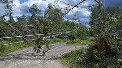
In 2011, a series of three storms passed through western Massachusetts and resulted in extended outages on a 69-kV transmission line in East Longmeadow, Massachusetts, U.S. In June 2011, an unprecedented tornado caused significant damage to the area. The tornado was classified as an EF3, one of the most powerful to ever come through the region. When crossing the transmission corridor, the tornado shifted course and began traveling alongside the corridor, leaving uprooted trees and broken structures in its wake. In August 2011, Hurricane Irene made landfall in New York and moved north through New England. The strong winds from the storm brought down trees again along the same transmission corridor, tearing down many structures.
Finally, at the end of October 2011, an unusually early snowstorm blanketed New England. The storm hit at a time when most of the leaves were still on the trees, adding an extreme amount of weight to the branches. Many of the branches could not handle the heavy snow loading and came down, including those along the same corridor. Poles broke under the weight of the trees, and the conductor was pulled from the structures, resulting in the third extended outage within five months.
In addition to the major storms, there had been a history of falling tree branches causing momentary outages on the transmission line. National Grid resolved to find a way to storm harden this line.
The Problem with Tall Pine Trees
The 12-mile (19.3-km) transmission line is supported by single wood poles with phases in a triangular configuration. It runs parallel with a second circuit for approximately 4 miles (6.4 km) in a 100-ft (30.5-m)-wide corridor. Further on, it occupies its own corridor for approximately 8 miles (12.9 km) in a much narrower 60-ft (18.3-m)-wide corridor.
The majority of the corridor is lined with tall pine trees, including many that exceed 100 feet in height. All of these taller trees can be easily broken by strong winds and heavy snow. The existing structures on the line were 40 ft to 55 ft (12.2 m to 16.7 m) tall. In the areas where the lines share the right-of-way, a single fallen tree could take out both lines, which would result in the loss of a local substation.
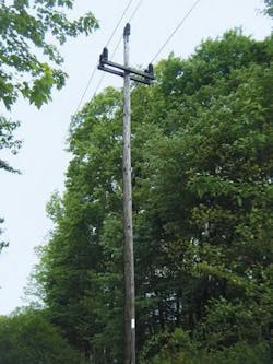
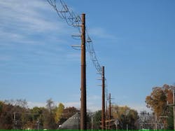
This is typical of the tall trees that are adjacent to the transmission line that experienced all of the outages in 2011.
Fortunately, there was already a project in progress to upgrade a portion of the line to 115 kV. The upgrade included taller structures, larger phase spacing and the addition of shield wire for added protection. However, this project was performed to feed a new substation. That meant only 10 miles (16 km) of the 12 miles of the line needed to be upgraded, leaving 2 miles (3.2 km) of the line exposed to potential tree damage — one mile in the solitary right-of-way and a second mile in the shared right-of-way. Several options were considered to address the storm damage concerns:
• Option 1: Do nothing. This was not a realistic option. The storms had exposed the weaknesses of the system. Something had to be done to increase the reliability of the lines.
• Option 2: Refurbish the line. Replace deteriorated assets and update the line to meet current standards. However, it was determined that this approach would not address the existing reliability issues.
• Option 3: Rebuild the line with taller structures. This alternative would address the concerns related to trees falling on the line. However, the new structures would need to be significantly taller given the height of adjacent trees. If the new structures remained in a triangular configuration, they would lose the lightning protection offered by those adjacent trees, thereby creating the need to use a shield wire. This would require even taller structures and have greater horizontal phase spacing. The footprint needed to accommodate this configuration would not fit on the existing right-of-way.
• Option 4: Expand the right-of-way and remove danger trees. The rights for the additional land for this option would be extremely difficult to procure. In addition, the amount of tree clearing required would likely have engendered concern among the abutting property owners and town officials.
• Option 5: Do a 69-kV spacer cable rebuild. The 69-kV spacer cable is a fairly new technology and has only been employed in a handful of locations. This installation was the first in the northeast United States. Spacer cable offers a stronger wire system than typical bare conductors. The additional strength of the messenger cable helps to resist damage from larger falling branches and small trees. The conductors also are covered, which reduces outages caused by momentary phase-to-phase contact. The spacer cable configuration has a narrow footprint, enabling more clearance between the conductors and the trees. The challenge with this design is the spacer cable and messenger cable structurally would overload the existing structures.
National Grid decided a combination of the spacer cable option and the refurbishment option offered the greatest opportunity to reduce outages and increase the reliability of the line. Multiple spacer cable solutions were investigated with varying lengths of conductor being installed. In the end, it was determined the most prudent course of action was to install the new spacer cable along a 1.5-mile (2.4-km) portion of the line where tall trees presented a danger. The remaining half-mile portion of the line, which ran through residential areas, would be refurbished using the existing wire.
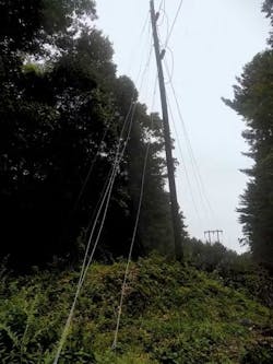
This typical dead-end structure is leaning and needs maintenance.
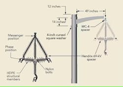
Spacer cable consists of three covered cables and a single messenger wire. The messenger wire carries all the tension and supports the conductors. This wire also acts as a neutral and shield wire. The full system is strung through spacers at suspension structures, which are 4.7 ft (1.4 m) tall with each cable attached to dead-end structures through horizontal post insulators. Additional spacers are used on either side of the dead-ends to facilitate spreading the cables apart toward the structures. It was recommended double spacers be used, but instead, triple spacers were used for extra reliability.
The manufacturer, Hendrix Wire and Cable, was consulted during every phase of the design and was instrumental in solving many issues that arose during project development. The original concept was to install new wood structures, but it was quickly determined this would not be possible without greatly increasing the number of structures on the line. Typically, 69-kV spacer cable structures consist of a single pole with a single davit arm that supports the messenger and conductors. The cables are covered, so the conductors are heavy. This results in large overturning ground-line moments. To design for these types of loads, small spans on steel structures were used. Dead-end locations required concrete caisson foundations.
Because of the narrow right-of way, the center line of the conductors had to stay in its existing location. The single davit arm design for the spacer cable meant the new structures would have to be offset from the center line of the existing ones. To ease constructability, the new structures were designed to be tall enough to be installed prior to removing the existing ones and to ensure the new conductors would not sag into the existing lines. It also meant designing the new structures to be able to carry the existing conductors if necessary.
The structures were designed with vangs at the existing conductor elevation so the existing conductors could be attached to the new poles, if needed, and the line could remain in service. This feature was never used because outage constraints were not as restrictive during construction as initially anticipated.
Diagrams show spacer and wire positions (left) and a typical structure with spacer (right).
Several challenges arose during the design phase of the project. There is a tap junction on the line where a couple of switches are located and the two existing lines cross each other. Installing spacer cable through this section meant that the switches would have to be replaced and work would be required on the other line to maintain clearances. Therefore, the decision was made to leave the conductor between the switches as standard bare aluminum conductor steel-reinforced (ACSR) and to reuse the switches making construction through this section much easier without impacting reliability.
The area just outside the local substation was also challenging. The substation is located adjacent to a Massachusetts Department of Transportation (DOT) storage area just before the line spans a reservoir. In the storage area, the structure heights needed to be minimized as much as possible. And, the line turned in this area with more than a 90-degree angle. Normally, this would require a structure with a caisson foundation. But, since DOT would not allow installation of this type of foundation on its property, a direct-embedment steel structure was installed. The corrugated metal pipe National Grid installs for all direct-embed structures was backfilled with concrete. The conductor for the last two spans on the DOT property was also left as ACSR to allow for shorter structure heights.
Around the reservoir, the spans were too long for the suspension-structure davit arms. Therefore, it was necessary to design all five structures in this section as dead-end structures.
This is a detail of a lightning arrester installation at a structure with spacer cable on one side and bare conductor on the other.
With the design complete, construction commenced in September 2015. While drilling the foundations for the dead-end structures, the foundation contractor encountered an abandoned quarry. Rock coring was expected, but large air voids were not. The holes were in danger of collapse as drilling continued. The structures proposed in the abandoned quarry were relocated. Because of abutting property owner requests, several other structures needed to be relocated before stringing could begin.
Hendrix supported the project for the duration of the construction. The company held training for the crews prior to the start of the spacer cable installation and sent representatives to the right-of-way daily while stringing operations were in progress.
There were some small difficulties during the cable installation. The cables are large and stiff, making them difficult to bend. Stringing was a challenge in areas where the cable needed to turn sharply between closely placed structures, and it was a struggle to get all three-phase conductors onto the lead trolley. The three Kellum grips needed to be attached to a single large bolt. It took longer than anticipated to complete this setup, but once it was ready, the stringing went smoothly. Construction was completed in December 2015.
There have been no issues with the conductor since its installation. National Grid is monitoring its performance and, depending on how it performs, will consider using this type of conductor in other locations with similar tree-contact problems.
Lightning arresters were installed at every structure that transitioned from bare conductor to spacer cable to prevent any surges in the bare conductor sections from entering the sections of spacer cable. Without the arresters, issues could develop at the interface between the wire types.
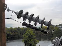
National Grid’s standard practice is to install porcelain insulators rather than polymer for transmission lines. However, for spacer cable, polymer insulators are recommended for the horizontal line posts for dielectric compatibility. To follow National Grid practices and avoid dielectric complications, a special trunnion clamp was designed to enable the use of porcelain post insulators. The spacer cable attaches to the insulator through this specially designed clamp.
Acknowledgement
The author would like to thank Hendrix for its contribution to this article.
Daniel White joined National Grid in 2009 and is currently a lead engineer in the transmission engineering department. He is a professional engineer in Massachusetts and holds a MS degree in structural engineering. White has performed the engineering on a number of transmission projects throughout New England and New York.
