CenterPoint Energy Houston Electric’s (CNP’s) service territory consists of coastal areas, highly industrial areas (such as the Houston Ship Channel), rural areas and the congested Houston, Texas, U.S., business and residential districts. Obtaining rights-of-way for serving new loads is a challenge worldwide, but CNP faces particularly acute challenges.
Part of the utility’s strategy for meeting load growth is to rely on high-temperature low-sag (HTLS) conductors to increase ratings. CNP tested and approved the use of aluminum conductor, steel supported (ACSS) at 345 kV in 2000 and pioneered the installation of Southwire’s ACSS/HS285 in 2007 (“First U.S. Installation of New ACSS Conductor,” Transmission & Distribution World, December 2007). CNP quickly accepted the challenge to become the first commercial installer of Southwire’s new stranded carbon-fiber-core C7 overhead conductor with Celstran CFR-TPR.
Candidate Line Selection
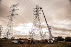
A 138-kV line in a rapidly growing area northeast of Houston, between the communities of Crosby and Mt. Belvieu, was scheduled for upgrade. This area supports natural gas storage facilities, and the industrial customers in the area have added six new 138-kV substations in the last year. The existing line was a single-circuit twin bundle using 927.2 kcmil aluminum conductor, alloy reinforced (ACAR) installed on double-circuit vertical steel towers. This location was an ideal candidate for a near-term demonstration line because the structures had an open-circuit position ready for the new installation and construction crews were already working in the area.
The line is in a rural industrial area and crosses relatively flat terrain. The line was selected because it represented the best near-term opportunity to install several miles of both types of the new conductor. Another consideration is that the design allows connecting one or both sides to form the circuit. This could allow the loading of the C7 conductor closer to its thermal limits and validate the capacity ratings and low-sag characteristics under actual operating conditions.
Line Design
After determining the conductor had passed suitable tests, CNP requested sag and tension information to perform line designs using PLS-CADD. The line was modeled with the new 995-kcmil C7 conductors (Drake-equivalent 1.108-inch [28-mm] diameter), and tensions were chosen that placed the conductor at about the same sag as the parallel existing ACAR conductor under normal unloaded conditions.
The line is based on 800-ft (244-m) span construction, and the 995-kcmil ACCR/TW/C7 with aluminum-zirconium (Al-Zr) used in the first section had no trouble meeting the sag requirements for the full range of temperatures and loads when sagged at 20% of RBS under the initial unloaded condition. Compared to the existing ACAR on the other side of the towers, the ACCR/C7 had more than 10% less sag at the rated temperature for the conductor while having the same sag at normal unloaded conditions.
The second section used the 995-kcmil ACCS/TW/C7 with O-temper aluminum, and the tension was based on matching the first section. This resulted in slightly more sag in the ACCS compared to the existing ACAR on the other side of the towers under normal conditions, but, at the rated temperature, the sag is about 30% of the sag of the ACAR.
CNP rates ACSS at 180°C (356°F) continuous and 200°C (392°) emergency, and plans to use these same temperatures for rating the new C7 conductors. Southwire recommends limiting the ratings to 180°C continuous and 225°C (437°F) emergency for rating the C7 conductors.
Crew Orientation
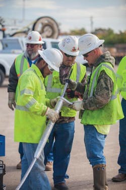
New technologies sometimes require special handling or changes in installation procedures. CNP requested all stakeholders to attend a training session. Representatives from Southwire, AFL and Celanese attended a preinstallation seminar to brief the line crew and engineers on what to expect with the new conductor. The utility met an early design goal when it was determined the installation process and equipment needed were basically the same as ACSS.
As with most transmission conductors, block and tensioner sheave sizes have to be large enough to not damage the conductor during installation. Polymer composites are stronger than steel in tension but softer than steel in all directions other than tension. Steel is ductile and is deformed before it breaks. Carbon-fiber composites like the C7 core accept load up to the breaking point with essentially no permanent deformation. A damaged steel core may serve for a long time, whereas a damaged singe-strand composite core will likely break. The new stranded-core design makes this conductor flexible and resistant to damage from the stresses of installation. Much like stranded conductors, some caution is still needed to ensure the conductor does not experience extreme bending.
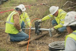
As part of the training session, sample compression deadends were installed using AFL Global’s installation guide. The pressing equipment for installing the compression fittings is the same as for other conductors with only the 100-ton press being required because of the large diameter of the connectors. The compression deadends installed during the training session were tested and all of them held above the rated breaking strength of the conductor.
The crew installing the C7 conductors also performed testing of the pulling and tensioning grips, applying loads that were about double the sagging tension planned for the installation. The grip testing was done on both types of the conductor as well as some ACSS. Most of the various vendors’ grips were tested and no problems were observed with any of them. The Kellems and Klein grips were selected for this installation.
Conductor Stringing
In November 2013, in pleasant fall weather, the first C7 overhead conductor came off its reel and into a transmission system. The installation went according to plan. The only snag was a short delay to clear a swivel that got hung up on the entrance block at the start of the pull.
To install the C7 conductor, crews followed the standard equipment and stringing techniques recommended in IEEE Guide 524, Guide to the Installation of Overhead Transmission Line Conductors. The size of stringing blocks, tensioner bull wheel size and type, and conductor reel and tensioner setup positions require particular attention to avoid extreme bending or crushing loads that could damage the stranded core. The conductor stringing used back-to-back Kellems grips to allow the entire section to be strung using a single setup location with the tension splices installed before bringing the conductor up to final sag.
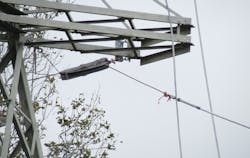
Compression connectors supplied by AFL Global were installed for in-line and deadend applications. Procedures and tooling for installing the C7 connectors is the same as for ACSS. CNP used the AFL Global HiBus suspension clamps that were qualified as part of the sequential mechanical test on the ACCR section and standard armor rods and suspension clamps on the ACCS section. Stockbridge vibration dampers where installed to protect the conductor from Aeolian vibration based on recommendations suppled by AFL Global.
An audit of the installation equipment found one undersized pulley on the conductor trailer, which was replaced with one meeting recommended diameter. Southwire initiated a new sheave test in accordance with IEEE 1138 requirements. Testing proved that 30 passes over a 16-inch (406-mm) sheave at a tension of 7,170 lb (3,250 kg) and a breaking angle of 30 degrees did not degrade the conductor’s tensile strength.
The additional testing did confirm that bolted sector clamps or quadrant strain clamps are unsuitable for full-tension deadends, as the combination of a tight radius and pressure from the U-bolt clamps reduced the conductor strength to 70% of its nominal rating on the ACCR/C7.
The installation was completed in two phases. The first was a 2.6-mile (4.2-km) section where 995-kcmil ACCR/TW/C7 was installed. A second 3.3-mile (5.3-km) section was fitted with 995-kcmil ACCS/TW/C7. For practical purposes, the conductors are identical in size and weight. Southwire is offering O-temper (ACCS) for installations in light loading where extremely low sag is important. Similar to ACSS’s fully annealed aluminum, ACCS is designed so conductor tension is predominantly on the core, which has extremely low thermal expansion. The problem comes when designing for ice and wind loads, where conductor sag can exceed high-temperature sag due to the elongation of the carbon fiber core under loading conditions. Modeling done at Southwire found the strength and elastic modulus of the ACCR, which uses an Al-Zr alloy, was sufficient for even extreme ice and wind loads. The stranded carbon-fiber core continues to limit the high-temperature sag, but the Al-Zr version will sag more than the O-temper version at high temperature. CNP wanted to use both so as to have both options available in future projects.
The ACCS section was installed in April 2014 and both sections were energized in May 2014.
Other Projects
The completion of the demonstration line and the coming operating experience will provide CNP with a full range of options for meeting the demands of delivering energy in its congested service territory. For price and performance, all-aluminum conductor (AAC) and aluminum conductor steel reinforced (ACSR) are still good choices for lines that do not have high loading.
At CNP, ACSS is used on most new lines and for upgrading existing lines where increased sag is not an issue because of the higher capacity achieved. The HTLS options will now include Southwire C7 conductors when increased sag is an issue. The new C7 conductor should allow for upgrading more lines without having to replace structures. Almost two-thirds of the cost of line upgrades that require structure replacements can be saved if the structures do not have to be replaced. In the end, having more options available to upgrade a line should help to keep electric rates lower for the consumer.
Acknowledgment
The author would like to thank Paul Springer and his team at Southwire for their support in making this a successful installation.
Chester Kowalik ([email protected]) is a senior consulting engineer at CenterPoint Energy Houston Electric, LLC with 38 years of experience in the transmission line design and planning areas. He is a graduate of Texas A&M and a registered professional engineer in Texas. He serves as an advisor on the Electric Power Research Institute Transmission Line Design task force and the EPRI HTLS Conductor task force. Kowalik worked on the initial installation of ACSS at CNP in the late 1990s and most of the projects since then.
Companies mentioned:
AFL Global | www.aflglobal.com
Celanese Corp. | www.celanese.com
CenterPoint Energy | www.centerpointenergy.com
Southwire | www.southwire.com
Toray Industries Inc. | www.toraycfa.com
Sidebar: C7 HISTORY
The electric power industry has long been in search of conductors that exceed the already excellent performance of conductors with stranded-steel cores. Invar offers zero thermal expansion but fails to match the tensile strength of steel. Other types are expensive or have experienced line breaks.
Southwire spent considerable effort searching for the next generation of materials for overhead conductors. Nanotechnology developments are encouraging, but for the practical future, only ceramic fibers and carbon fiber offer the best properties.
In 2008, Southwire partnered with Celanese Corp. to develop a new core targeted specifically to the overhead line application. The result of the partnership is the C7 overhead conductor with Celstran CFR-TPR.
C7 conductor performed beyond expectations in rigorous testing and was finally ready for commercial introduction. CNP and Southwire have a long history of deploying innovative technologies, so CNP’s need for a high-performance conductor provided the perfect opportunity to deploy C7 conductor in an operating overhead system.
Due Diligence
Celanese is a worldwide manufacturer of advanced composites, but it previously did not have a footprint in overhead transmission products. Celanese took the lead from Southwire on the demands of this application. A multi-stranded core, similar to steel-core designs, was an early requirement. A stranded core provides for flexibility and tolerance for bending, and in addition, there is structural redundancy against a catastrophic failure should a single strand become damaged for any reason. The requirement is not typically met with carbon-fiber-core designs.
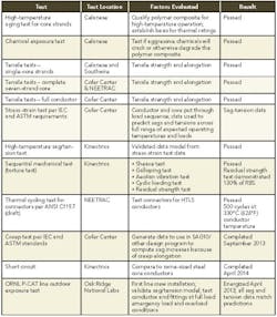
Celanese picked a commercially available carbon fiber: T700 from Toray Industries, a leading manufacturer in Japan. Celanese’s expertise and experience led to the selection of Fortron polyphenylene sulfide for the polymer matrix. For overall protection of each core strand, the world’s toughest known polymer, polyetheretherketone (PEEK) is used for a protective capping layer. PEEK has best-in-any-class chemical resistance, thermal resistance and abrasion resistance. Confident the optimum core design was at hand, Southwire undertook rigorous conductor and strand testing at its Cofer Technology Center and other nationally recognized independent labs (as summarized in the table).

