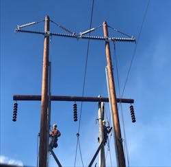
Optimization of Transmission Line Structures Using Braced Post Insulators
Modern transmission line projects face several challenges with different priorities than projects in the past. There is now more emphasis on reducing environmental impacts, producing aesthetically pleasing designs, public acceptance, lowering life cycle costs and minimizing right-of-way widths due to ever rising land prices. All this needs to be considered while maintaining a safe, robust, and reliable design.
One option that has gained popularity over the past few decades is the use of post and braced post insulators instead of traditional suspension strings for 69kV to 240 kV applications. Depending on the location and voltage class of a project, braced post insulator designs might prove to be the optimal design option for designers. There are now several manufacturers that can provide custom post insulators tailored to the specific needs for any structure design.
Optimal Head (Phase Configuration) Design
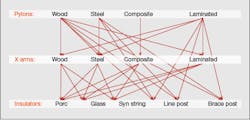
In our present state, simplicity is difficult to obtain only because over the years we have created a complex web of choices or what one can refer to as the ‘MENU’ in the graphic. The secret to simplicity is to ‘regularly’ review new and legacy material and designs with a ‘holistic analysis’ approach and remove what is no longer appropriate. This will ensure a lean and effective menu.
Labor costs are the highest component of project costs, therefore promoting designs that decrease labor is key. By reducing the ‘menu’ it also provides a tremendous opportunity to reduce the appropriately corresponding materials kept in stock to a minimal requirement.
There are six single pole 138kV tangent structures in AltaLink’s current ‘menu’ that functionally serve the same purpose. Two are holistically more efficient and cost effective than the other four, so why stock material for all six when two will suffice for greenfield, brownfield and operational maintenance remediation including
urgent and emergency repair?
Not only are post designs simple, but they are also very versatile. Designing with posts allows greater head design flexibility to manage many environmental, manmade and design adversities with the same material and multiple configurations (Modular Design).
Post and braced post designs manage height and right-of-way restrictions by eliminating the need for traditional I-string insulators. Vertical phase and circuit spacing can be easily reduced or increased as required with little effort (shorter spans can use less vertical spacing which will then require shorter poles). Post insulators have the versatility of being used on wood, steel or composite structures. They can be used for 138kV single circuit or double circuit framing and can also be used on monopole or H-frame structures without any additional requirements. Post insulation can be used to limit conductor swing out, which may avoid the need to widen an existing right-of-way or cut additional trees.
Line Optimization Study Results
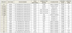
The line optimization studies (LOS) conducted over the past five years have been undertaken with the most robust analysis methodology in AltaLink’s history. The projects that have been analyzed to date are 138 kV and 240 kV, single and double circuit lines.
The mandate of the LOS was to be able to cost analyze multiple line design options simultaneously, which included multiple foundation types (direct embed, pipe piles, screw pile clusters, grillage, caisson), multiple pylon materials (wood, steel, composite, FRP, lattice), multiple conductor types (266ACSR to 1927ACSS), multiple ruling spans (150 m to 350 m) and with multiple line lengths (3 km to 58 km).
In all case studies, the results indicate post design (line-post or brace-post) on steel monopole for single circuit and double circuit 138 kV and 24 0kV was ranked the optimal design with ‘the same or better functionality’ and ‘with the same or better reliability at less cost’.
Customized applications: Insulated arms
Composite Insulated Cross Arms (CICAs) are not a new phenomenon. They have been on the periphery for quite some time, but have only matured to a viable solution over the past 10 years.
Insulated arms have been used in many different applications internationally and are considered viable options to AltaLink in multiple scenarios:
1. Replace lower arms on lattice towers to mitigate clearance issues.
2. Replace all arms on a lattice tower to mitigate Self Damping Conductor (SDC) corrosion issues and clearance correction.
3. Thermal uprating projects.
-Increase clearance by 2.2m (240kV application)
-Improves maintainability
• Can be worked on while energized
• Can be maintained from the tower
-Customizable so it can be used for multiple voltage levels and design applications.
-Improves insulation, better contamination management capability due to improved leakage distances, hydrophobic material and
self- encapsulating properties.
-Alleviates right-of-way constrictions (i.e. vintage half span line design methodology)
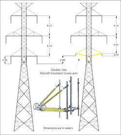
The analysis only included the CICA arms to replace the bottom phases of a double circuit 240kV lattice tower. A comparison between the original tower and the CICA modification is shown below.
Additionally, the phase separation from middle to bottom phase also needs to be evaluated. For this specific case AltaLink found the “L” tower to meet the Canadian Standards Association (CSA) phase spacing requirements.
CICA is a new product to AltaLink, therefore it will be closely monitored, especially the ‘triple point’ nose area for:
- Signs of erosion or arc burn on the surface of the composite insulator
- Signs of premature aging such as brittle fracture and cracking
- Signs of degumming, sealing failure, obvious slippage, etc. in the contact zone between the insulated core rod and the insulated casing
- Signs of damage on the grading ring, such as rust, arc burning, deformation and so on
- Signs of avian damage (i.e. pecking, streamers)
Customized Applications: Totally Insulated Framing System
A new concept being implemented at AltaLink is something called a ‘Totally Insulated Framing’ (TIF) system. This is a retrofit assembly designed to completely replace the crossarm and suspension insulators for H-Frame structures. This reframing solution is specifically aimed at addressing clearance violations without having to replace the existing structure.
The TIF assembly was first used on the AltaLink system for a clearance mitigation project on a 138kV line. For this project, the conductor needed to be raised by one meter to address a midspan violation. The project team decided that this would be a great pilot candidate for the new TIF assembly and installed on new poles.
The traditional ways of designing transmission structures with arms and suspended insulators are being challenged. These designs are proven and have been used for more than a century, but is there a better way?
AltaLink has initiated a Line Optimiz-ation Study process to assess the available design options and compare the old way with newer alternatives for new 138kV and 240 kV projects. This process has been fine-tuned over the last five years and has consistently shown that monopoles with post or braced post insulator assemblies are the optimal structure design. In general, AltaLink has found that braced post insulator designs reduce overall transmission project (lifecycle) cost by 10% to 15% over traditional suspension structure designs. Right-of-way width savings are harder to quantify as land prices vary by region, but it can be assumed that the land savings are proportional to the right-of-way width reduction.
By simply using braced post insulator assemblies, an equivalent H-frame structure can be reduced to single monopole with the added benefit of lower lifecycle and right-of-way maintenance costs. There is also evidence that the fire risk will be reduced due to contamination resistance (hydrophobic) of a composite braced post insulator.
Every utility should consider the use of braced post insulator assemblies and the benefits they can provide for new transmission line projects. Braced post insulators may not be the preferred solution for every project, as they do have their limitations, but they provide flexibility to meet the needs of external stakeholders that older designs of the past could not. Transmission utilities worldwide have been increasing the use of line post and braced post insulator assemblies over the past few decades because of the benefits they provide. Based off the line optimization results from AltaLink there seems to be good reason for this.
Kishor Kumar is a senior civil engineer with Engineering Standards & Support group at AltaLink L.P., A Berkshire Hathaway Energy Company. He is a registered professional engineer in province of Alberta and Ontario. Kishor has over 28 years of Transmission Lattice, steel, FRP & wood pole structures and line design experience. He is currently involved with ASCE Loading Standard and ASCE Foundation Manual committee.
Jeff Fraser is a senior civil engineer and a Transmission Lines team lead with West Power Energy, an engineering consulting firm specializing in transmission line design. He is a registered professional engineer in provinces of British Columbia and Alberta. Jeff has over 11 years of experience in the industry in all areas of Transmission line design with familiarity in the use and construction of steel, FRP & wood pole structures.
Dimitri Georgopoulos is a registered Professional Licensed Engineer in the Province of Alberta. He is a Consultant (REVMA Powerline Consulting) specializing in Transmission Line Optimization and Innovation. Dimitri has over 42 years of powerline experience with a core focus on insulation and its effect on optimizing structures and lines based on the principles of using a holistic value engineering analysis strategy.
About the Author
Kishor Kumar
Kishor Kumar is a senior civil engineer with the engineering standards and support group at AltaLink L.P., a Berkshire Hathaway Energy company. He is a registered professional engineer in the provinces of Alberta and Ontario, Canada. Kumar has more than 22 years of transmission lattice, steel and wood pole structures and line design experience. He is currently involved with the American Society of Civil Engineers Wood Pole and ASCE 10 Tower committees.
Jeff Fraser
Jeff Fraser is a Senior Civil Engineer and a Transmission Lines team lead with West Power Energy, an engineering consulting firm specializing in transmission line design. He is a registered professional engineer in provinces of British Columbia and Alberta. Jeff has over 11 years of experience in the industry in all areas of Transmission line design with familiarity in the use and construction of steel, FRP & wood pole structures.
Dimitri Georgopoulos
Dimitri Georgopoulos is a registered Professional Licensed Engineer in the Province of Alberta. He is a Consultant (REVMA Powerline Consulting) specializing in Transmission Line Optimization and Innovation. Dimitri has over 42 years of powerline experience with a core focus on insulation and its effect on optimizing structures and lines based on the principles of using a holistic value engineering analysis strategy.
