Prevent Gaps in Lattice Structural Analysis

Structural analysis of lattice transmission structures can be a time-consuming task. Fortunately, many tools and software aids have been developed to streamline the process. However, users must employ these tools with caution, making certain the underlying assumptions and checks being performed are appropriate and provide accurate results.
Using software aids without a thorough understanding of the underlying assumptions can leave analysis gaps and, ultimately, lead to lattice transmission structure member overstresses in the field. To help identify and avoid these concerns, it is important to know what issues are more commonly encountered and how to work through them to produce valid results.
Traditional Analysis Methods
To discuss nontraditional methods more clearly, it is important to establish what are considered traditional analysis methods. In the U.S., American Society of Civil Engineers (ASCE) 10 is the current design standard for lattice towers, and it provides great direction at defining what checks need to be considered. However, individuals still need to determine how to execute the required checks.
These checks are where software aids become relevant. As purpose-built software designed specifically for lattice towers in the utility industry, TOWER from Power Line Systems (PLS) has become a traditional software package proven to design and analyze lattice towers successfully. By incorporating national and international design codes, users can efficiently develop tower models and obtain meaningful analysis results. The nonstandard scenarios more commonly encountered fall outside the direction and capabilities of ASCE 10 and TOWER.
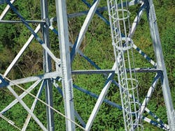
While unique modeling situations may be present in any tower, they are more common in older structures, particularly those designed prior to the implementation of ASCE 10 or its predecessor, Manual of Practice No. 52. Many of these structures incorporate poorly triangulated bracing schemes and member cross-sections that are no longer commonly used.
Knowledge and guidance on how to address these commonly encountered scenarios is helpful to recognize nontraditional situations and employ the proper analytical techniques.
Nonstandard Shapes
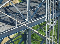
One common scenario is finding nonstandard shapes within towers. In this context, the term “nonstandard” refers to any shape that is not an angle, double angle, cruciform or rod.
While ASCE 10-15 provides guidance on calculating capacities for various types of shapes, the compression capacity checks within TOWER are only applicable to angle members. Specifically, the equations used within the program come primarily from section 3.7 of ASCE 10-15, “Compression Members: Angles.” Other shapes, including I-beams, channels, W-shapes and more, are not checked per the requirements of ASCE 10-15. While most new towers limit the use of nonstandard shapes, it is not uncommon to see them on older towers.
ASCE 10 does provide requirements on how to calculate the compression capacity for various shapes, which can be found in sections 3.8 and 3.9. Additionally, sample calculations can be found in Appendix B.
Three main differences exist in evaluating standard vs. nonstandard lattice transmission structure members:
- Additional calculations are needed to check torsional buckling, flexural buckling and torsional-flexural buckling.
- Different width and thickness ratio limits are used, which dictate the equation for the design’s allowable stress.
- Reduced area effects for shapes containing non-compact elements decrease allowable capacities.
Fortunately, ASCE 10 provides the user direction on how to address these issues, so it is straightforward to calculate a given member’s capacity. These calculations can be accomplished by hand or set up with an automated method using Excel, Mathcad or any other software capable of performing repetitive calculations. Because of the large number of members in most lattice structures, a spreadsheet format is recommended for calculating member capacities as an efficient means of evaluating multiple members.
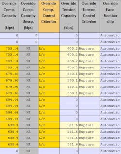
Once capacities are determined based on the appropriate ASCE 10 requirements, TOWER includes an option for inputting a member’s compression capacity as an override of the software-generated value using the table for members’ capacities and overrides. TOWER then compares this capacity limit to the force within each member and determines percent usages.
Nonstandard Material
Another area to be mindful of is the use of nonstandard materials—any material that is not steel—within lattice structures. The most common nonstandard materials encountered are aluminum and wood.
For these scenarios, keep in mind ASCE 10 is applicable to steel structures only. Therefore, one of the first steps is selecting an appropriate guide or standard to use for calculating the member capacities. The goals of the structural analysis should be considered when selecting a guide or standard.
Current standards or guides should be applied for designing and analyzing a new structure. However, when analyzing an existing structure, either current guides or guides used in the original design can be employed. Owner input should be considered when deciding which guides should be applied, as there are multiple guides available to choose from and, many times, it is not known what guide or standard was used in the original design.

It also is necessary to update the material properties within TOWER. This update is especially critical for the modulus of elasticity value, as changes to this property will impact member deflections, which will modify the stiffness matrix and, ultimately, the force distribution in the individual members.
Once a guide is selected, the process for analyzing the nonstandard material in lattice structures is like that of evaluating nonstandard shapes. The chosen guide will be used to calculate the appropriate capacities of each member, and once again TOWER’s members’ capacities and overrides table will be used to input the updated capacities. Like the process for nonstandard shapes, a spreadsheet format is one of the most efficient ways to calculate the capacities of numerous members within the structure.
Bending Effects
Finally, it is important to consider the concept of bending effects within a lattice transmission structure member. Occasionally, towers requiring analysis contain nonstandard bracing schemes or loading conditions that induce moments within members. TOWER does not calculate or analyze stresses due to moments, since the program assumes the tower is properly triangulated. As a result, equations within the program are specified to check capacities related to axial loading only. Given this consideration, it is important to verify the structural capacity of members in bending using tools outside of TOWER.
For lattice transmission structure members experiencing bending in addition to axial loading, the applicable equations are outlined in sections 3.12 and 3.13 of ASCE 10-15. These equations are set up to check a given member’s utilization ratios. As a result, the axial utilization of a member influences the remaining capacity to resist flexure and vice versa. In other words, if a given member experiences a small axial load relative to its axial capacity, the member will be able to handle a significant flexural load. However, if the same member is loaded axially near its axial capacity limit, it will only be able to accommodate a very small flexural load before becoming overutilized.
While this method of checking combined loading is not unusual, it does present a challenge when checking multiple load cases. Essentially, each member’s utilization ratios must be checked for the forces from each load case separately, to ensure the member is not overstressed. This process is more cumbersome when compared to the typical axial checks, in which a member’s axial capacity does not change depending on the magnitude of axial force present in the member.
In addition to calculating member utilization ratios, an alternative method should be used to determine the forces and moments present within members subject to combined loads, as TOWER does not require enough information from the user to complete analysis on members subject to non-axial loading. Specifically, the TOWER Version 14.0 manual states the following: “Beam elements in TOWER are not intended to give moments that can be used for the calculation of accurate bending stresses in the angles, as the program does not have the ability to model the correct eccentricities of each connection and to provide the actual orientation of the member around its longitudinal axis in space.”
As a result, it becomes necessary to use a software package that can accurately account for bending when distributing loads within members. Hand calculations may be used to determine the maximum forces within a member, but given the number of members present in most lattice transmission structures, alternative software aids are recommended.
The end goal is to determine the combined loading profiles (such as axial, shear and moment) of the structure members. After the member loadings have been determined, the values can be placed into a separate computational spreadsheet to evaluate the combined stresses and determine whether the utilization equations from ASCE 10 are satisfied.
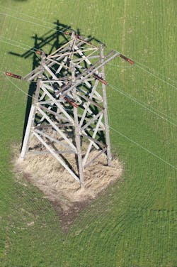
Perhaps the best way to illustrate this point is with an example. The scope of this example is replacing an existing wood cross arm with a new steel member. The configuration of this tower includes cantilevered ends of the cross arm. In addition, no bracing is present at the center of the cross arm where the middle insulator is located.
Therefore, the reason this particular tower does not lend itself well to standard analysis in TOWER is the cross arm is functioning as a continuous beam loaded primarily in bending. Evaluating a single heavy-ice case (with no wind, one inch of ice and a temperature of 0°F), TOWER reports this arm is utilized at 0.31%. TOWER also issues the following warning: “A potentially damaging moment exists in the following members (make sure your system is well triangulated to minimize moments).”
By developing a RISA-3D model and employing the equations from ASCE sections 3.13 and 3.14, it was determined this cross arm actually is utilized at 89%. The reason for the large discrepancy: TOWER is only checking axial capacity. This correlates well with the RISA-3D model, which provided an axial usage of 0.3%. The remaining 88.7% utilization is attributed to bending demands on the arm, which TOWER does not consider.
This example illustrates how analysis gaps can be particularly dangerous if the output of a software program is taken at face value without understanding its capabilities and limitations.
Eliminate Analysis Gaps
The analysis of lattice towers that require nontraditional modeling methods has become increasingly relevant in recent years. There are multiple factors driving this trend, including the aging of transmission infrastructure and increased difficulties around the permitting process and obtaining rights-of-way for new lines.
These factors have resulted in transmission line owners placing increased emphasis on using existing lines to transmit additional power and new communications. This emphasis has led to a heightened demand to analyze existing lattice structures, which is where these issues are most common.
Engineers need to be competent in understanding what checks software programs are performing and especially aware of instances where software programs could be leaving analysis gaps. Also, engineers need to be prepared to recognize these analysis gaps and apply nonstandard analysis methods, as necessary, to bridge the gaps and complete proper structural analyses.
Kevin Wortmann, P.E. ([email protected]) is a transmission line engineer who consults with utility owners to design and maintain transmission line assets. For the last 11 years, he has worked at POWER Engineers Inc., where he aims to ensure clients’ top priorities are maintained while tailoring engineering solutions to address specific challenges. Wortmann holds licenses as a professional engineer in Missouri, Nebraska and Ohio, and as a structural engineer in Illinois. He graduated with a BSCE degree in 2009 from the University of Missouri-Columbia.
Ryan Hann, P.E. ([email protected]) is a transmission line engineer for POWER Engineers. Over the past eight years, he has assisted various utilities in evaluating, designing, and maintaining existing or new transmission assets. Hann holds a professional engineer license in Missouri and Illinois. He graduated from Southern Illinois University, Edwardsville, with a BSCE degree in 2012 and a MSCE degree in 2017.
About the Author
Kevin Wortmann
Kevin Wortmann, P.E. ([email protected]) is a transmission line engineer who consults with utility owners to design and maintain transmission line assets. For the last 11 years, he has worked at POWER Engineers Inc., where he aims to ensure clients’ top priorities are maintained while tailoring engineering solutions to address specific challenges. Wortmann holds licenses as a professional engineer in Missouri, Nebraska and Ohio, and as a structural engineer in Illinois. He graduated with a BSCE degree in 2009 from the University of Missouri-Columbia.
Ryan Hann
Ryan Hann, P.E. ([email protected]) is a transmission line engineer for POWER Engineers. Over the past eight years, he has assisted various utilities in evaluating, designing, and maintaining existing or new transmission assets. Hann holds a professional engineer license in Missouri and Illinois. He graduated from Southern Illinois University, Edwardsville, with a BSCE degree in 2012 and a MSCE degree in 2017.