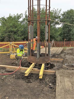
AEP's Construction of Shaft Foundations During Live-Line Conditions
Deenergizing transmission facilities to accommodate construction tasks requires careful planning, often affecting the line design. In the age of rebuilding transmission, outages are shorter and more difficult to obtain. Implementing design components that do not require outages serves to reduce reliance on outage schedules and provide flexibility in the construction schedule, which may result in overall cost savings.
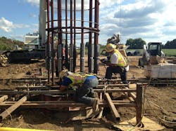
To reduce the reliance of foundation construction on the outage schedule, American Electric Power Co. Inc. (AEP) and DiGioia Gray & Associates LLC (DGA) co-developed a method to increase the construction productivity of drilled shaft concrete foundations during live line conditions. This method mechanically splices full-depth anchor bolt cages — so multiple, but shorter, sections may be set safely beneath energized lines. This unique foundation construction approach has enabled foundation contractors to install drilled shaft foundations successfully with limited overhead clearance to energized conductors and better meet project schedules.
Also presented are the results of a testing program used to verify splice strength, details for design and constructability considerations and a discussion of lessons learned from the installation of mechanically spliced full-depth anchor bolt cages.
Testing Program
A testing program was necessary before the bolt cage splicing could be used in design. Anchor bolt cages for transmission line structures typically are designed using #18 jumbo-sized (#18J) American Society for Testing and Materials (ASTM) International A615 grade 75 threaded rebar. Common mechanical splices are available for sizes of rebar up to #18. However, information regarding the use of #18 mechanical splices on #18J rebar was not available. Therefore, AEP implemented a testing program of the #18J bars and #18 splices—to ensure conformity of the proposed combination to current codes and construction tolerances.
Mechanical splice specimens from two manufacturers were included in the testing program. Project design criteria mandated mechanical splices satisfy American Concrete Institute (ACI) 318-14 section 25.5, which specifies the mechanical splice have a tensile strength of 125% of the specified yield strength of the rebar. Both mechanical splice products were bolted-type splices. The testing program was designed with variable gaps from the end of the rebar to the centering pin. Also, to establish splice fabrication and installation tolerances, the program was designed with variable orientation of the rebar ribs to the tightening bolt.
A total of 12 tests were conducted, six from each manufacturer. All tests met the code requirements of achieving 125% of the specified yield strength equal to 93.75 kilopound per square inch (ksi) (646 MPa), assuming a design stress area of 4 sq inches (25.8 sq cm). The failure mode for all specimens was the end of the rebar slipping out of the splice. The successful tests enabled AEP and DGA to move forward with the spliced anchor bolt cage designs.
Design and Constructability
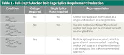
Not all foundations on rebuild projects are ideal candidates for spliced anchor bolt cage construction beneath energized lines. For example, AEP limited the approach to situations where only one level of splices was required, meaning the cage could be divided into no more than two segments.
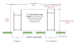
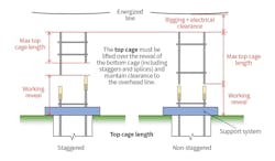
Multiple splice locations increase the potential for problems in fitting the cage segments together and complicate construction practices, which increase risk during installation. Therefore, a procedure was developed to evaluate each foundation. It included preliminary sizing of the top and bottom anchor bolt cage segment lengths, as well as confirming the foundation could be installed with a single splice location.
Further Considerations
After the applicable foundations have been identified, the final splice locations must be selected. Each cage will have a zone where the splice can be placed successfully. The following recommendations are provided to simplify fabrication and construction:
- Maximize the bottom segment length — This reduces the weight of the suspended top section when installing the mechanical splices.
- Shear tie reinforcement spacing — If the splice can be located between the shear tie reinforcement, this will avoid having to rearrange shear ties during construction.
- Template clearance — To avoid conflict of the mechanical splices and anchor bolt cage templates, the splice location should be selected with consideration of the design and spacing of the templates.
- Cage segment consistency —Splices may be located for consistent top and bottom cage lengths for several foundations.
Spliced cage designs present more opportunity for conflicts to occur between cage templates, the splices and the installation support system. A process for identifying conflicts is recommended — after refining the cage segment lengths, but before construction.
The engineer should review cage fabrication drawings to confirm the cage lengths satisfy the foundation design and identify potential conflict between the cage templates and mechanical splices. Also, the installation support system includes the cage lifting points and support frame used to hold the bottom cage section in the hole. The anchor bolt cage sections must be braced properly while lifting and during splice installation. The support system should be developed by the foundation contractor, who may propose using the template or other parts of the anchor bolt cage as a structural component of the support system. The support system should be reviewed by the engineer and anchor bolt supplier.
Finally, prior to finalizing the spliced anchor bolt cage design, the manufacturing tolerances of the anchor bolt cages and mechanical splices should be confirmed by the respective suppliers, to identify and resolve potential dimensional conflicts.
Lessons Learned
Through implementing mechanically spliced anchor bolt cages on several projects, AEP overcame challenges and learned lessons. Importantly, the most effective way to mitigate the risk of an impact to the project schedule is through collaboration among project management, outage planning, engineering, suppliers, and construction personnel (internal and external) during the design, procurement, and construction planning phases of the project.
Additional lessons were as follows:
- The splices would accept an overall rebar diameter of 2.5 inches (635 mm), inclusive of ribs. However, fabrication tolerances for #18J rebar permit a maximum diameter exceeding 2.5 inches. Project experience showed some, but not all, #18J bars would fit into the splices. This issue was mitigated by specifying a 2.5-inch maximum overall diameter on the anchor bolt cage drawings. The anchor bolt supplier created a template that slipped over each anchor bolt to verify the 2.5-inch dimension within the splice zone (prior to assembling the cages) and used a grinder to reduce rib height, when necessary.
- Field experience showed some end preparation of the anchor bolt cages would improve field fit-up greatly. To simplify splice installation, AEP requested that the splice manufacturer take extra care to clean out leftover material from inside the splice, as well as specified chamfering the ends of the rebars or anchor bolts to be inserted into the splice.
- Field crews found marking the insertion length of the anchor bolts was a simple way to verify proper splice construction and an easy method for inspection.
Costs and Efficiencies
Labor and material costs to install mechanically spliced #18J full-depth anchor bolt cages make them more expensive than cages designed without splices. However, using splices may reduce the overall project cost or provide more value than the additional cost of installing the splices:
- Reduces the amount of new right-of-way purchased, by building new transmission lines closer to lines within the existing right-of-way
- Maintains revenue, by keeping the existing line in service
- Reduces the dependence of the schedule on foundation construction outages, thus providing an earlier in-service date.
When used in appropriate situations, the benefits of using mechanically spliced cages should be expected to exceed their installation cost.
After multiple, successful installations, it was clear that frequent collaboration between engineering, the owner, suppliers and the foundation contractor early in the design and preconstruction phases most effectively mitigated design changes and construction difficulties.
Although mechanically spliced cages require additional collaboration and have a higher upfront cost, using them ultimately provides important time and cost efficiencies for rebuild projects.
About the Author
Aaron P. Darby
senior engineer
Aaron P. Darby, P.E., is a senior engineer in the Transmission Line Standards Department at American Electric Power. He has more than seven years of transmission engineering experience at American Electric Power. The past five years he has focused on structural and foundation standards development which includes the modeling, design, testing, and reinforcing of transmission structures. Darby received his BSCE from Virginia Tech, with an emphasis in Structural Engineering, and is a Professional Engineer in Virginia. Aaron is a member of ASCE.
