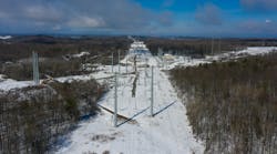
Underground transmission installations recently have become more commonly used for solving difficult river crossings in the utility industry. Duke Energy Progress’ installation of a 230-kV underground transmission cable crossing was not an industry first nor an evolution of the design process. What made this project special was the utility had no history with underground transmission in this service territory.
The project team rightly anticipated pumping plant maintenance would be both a new and ongoing task for the local electricians and relay technicians, so the employees accountable for maintenance were included in the engineering and design process to specifically address the project from an after-construction perspective. A conscious effort was made to consider and evaluate options that directly impacted the field personnel and maintenance of the line after construction was complete.
Justifying the Need
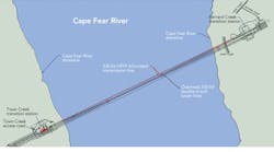
In early 2009, Duke Energy Progress identified the need to mitigate the potential impact of a common tower failure on two 230-kV lines crossing the Cape Fear River in Wilmington, North Carolina, U.S. The two lines originate from the Brunswick Nuclear Plant and remain on separate structures except for the mile-wide river crossing on two 330-ft (101-m)-tall double-circuit towers. Failure of either of these structures would result in a significant output reduction to each 940-MW unit at the plant that could take several months to repair.
The project objective was to remove one circuit from the towers, cross the river at a new location and tie back into the original lines on each side of the river. Multiple overhead routes were considered, but, in the end, the utility decided an underground line would have less overall impact from easement acquisition, which would involve a lengthy environmental permitting process and acceptance from the U.S. Coast Guard, the U.S. Army Corps of Engineers and the Port of Wilmington. Although the cost estimates for the underground crossing were marginally higher, overhead concerns justified choosing the underground option.
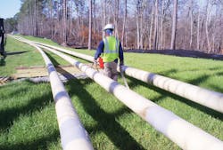
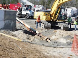
The design decision was made to install a high-pressure fluid-filled (HPFF) pipe circuit, consisting of two pipes for rerouting the line. Two pipes were necessary because of the high line ampacity. The cable used for the crossing was 2500 MCM copper.
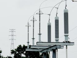
One interesting aspect to the project, the original overhead circuit crossing the river was to be left in place and act as a backup in the event the underground circuit needed to be de-energized. To facilitate this, two line switches were installed on each side of the river to allow transferring the load between the overhead and underground circuits.
Designing Through Collaboration
Duke Energy Progress used outside engineering expertise to complete the underground pipe, cable and pumping plant designs, while using internal transmission line, substation and relay engineering resources to integrate those designs. An independent consulting engineering firm provided technical oversight, and Duke Energy Progress transmission engineering personnel performed project management, environmental permitting, transition station/substation site design and overhead transmission design functions in house.
What occurs so often when utilities install new products, pieces of equipment or, in this case, an underground transmission line is this: engineering work is completed, projects are bid and awarded, contractors complete the installation and demobilize, the invoices are paid, the line is energized and, with a resounding yes, the project is considered complete. Often, the personnel charged with maintaining the system are left with the task of learning how to maintain the system on their own. This project proved to be an exception.
Duke Energy Progress’ transmission department includes an asset management group responsible for providing direct engineering field support to crews, creating preventive maintenance programs with justified inspection frequencies, writing specific maintenance tasks and related instructions, assisting with the development of training programs and providing guidance in specifying critical spare parts needed for field maintenance work groups in the department. Personnel from this group interfaced with the hands-on maintenance crew to identify areas that most impacted future periodic and preventive maintenance activities.
After making the decision to go with underground transmission on this project, and having no experience with that technology in North Carolina, Duke Energy Progress analyzed its Florida underground system and used best practices to integrate the two system philosophies.
At the start of the project, the utility had no previous experience with underground transmission technologies. Without legacy standards, practices and procedures in place, this allowed for the integration of the maintenance organization into the design process. After the merger with Florida Power Corp. in 2001, Duke’s technical field support personnel, who supported Florida and the Carolinas, assessed the underground transmission system located in St. Petersburg, Florida. This exposure made all the difference and prompted many discussions concerning options and preferences during the Cape Fear crossing design.
The Florida system was constructed primarily in the 1960s and includes three vintage Jerome pumping plants. Although the system is aged, it operates remarkably well and continues to be quite reliable. This assessment ensured the support personnel were prepared to contribute to the design discussion. A conscious decision was made to incorporate the best aspects of the Florida system into the Cape Fear crossing and improve on shortcomings.
Charting Interactively
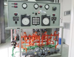
Although state-of-the-art programmable logic controllers (PLCs) are commonly used to record line pressures, tank volumes and nitrogen blanket pressures, the utility decided purchasing the old tried-and-true paper chart recorders was the right decision for this project. Circular paper charts easily show how the plant interactively operates, when the pumps run and how the fluid volumes change. Circular charts also are a great troubleshooting tool to use when problems occur. PLCs were not used on the Cape Fear project as they did not meet the objective of keeping the hands-on employees engaged with how Duke Energy Progress’ single pumping plant in eastern North Carolina operates.
Backing Up Power
Wilmington has seen more than just a few hurricanes. Power outages inevitably occur and are expected. The Cape Fear project was designed with this in mind.
The pump is powered by a 48-V battery system with two alternate ac sources. In the remote event of an ac power loss, an emergency nitrogen pump operates to keep the lines pressurized for up to 24 hours before requiring bottle replacement.
Signaling Alarms
Duke Energy’s Florida system was originally designed only to send either a minor or major alarm to the energy control center. The Cape Fear system sends all annunciator alarm points and analog data to the energy control center, including fluid volumes and pressures.
This is a significant improvement to the original Florida system design because, in the event of an emergency, on-call personnel can be given guidance to the correct course of action prior to arriving at the pumping plant.
Altering the Field Design
In spite of all the collaboration and planning, some field design changes were made to give the system a more user-friendly feel. Initially, there was not an easy method to disable tripping the cable circuit breakers without lifting wires and pulling trip circuits. Cutoff switches were added after consulting with the relay engineering group. This allows maintenance personnel to work on the cable pressure systems without running the risk of tripping a vital circuit.
Detailed Labels, Diagrams and Plans
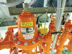
The pumping plant used on this project has well-labeled individual components. For example, the relief and reduced pressure valves each have minimum or maximum pressures with labels stamped on chains, such as V24B (valve 24, line B). All pressure switches, pumps and gauges are also labeled. This is extremely important to electricians when faced with a troubleshooting situation or when periodic maintenance is performed. A detailed plant flow diagram is attached to the wall for quick reference.
These aids are needed to complete the step-by-step maintenance job plans that have been developed to functionally test the plant operation and simulate various tripping and low-/high-pressure alarm scenarios.
The electrician is required to sign the completed job plan to acknowledge all steps were performed. Readings that are trended, such as cathodic protection voltages, are captured on notebooks and later entered into the maintenance computer database. These job plans track the status and changes among equipment and allow for the trending of all recorded measurements. This tracking and trending protocol helps with identification of problems before failures occur.
Storing Spare Parts
Although most pumping plant parts are generally available within two weeks of order, the critical nature of this line necessitated that all electronic parts have duplicate spares stored on site. Several other longer lead-time items that have spares include a motor, a pipe splice kit, a spare pothead with a rebuild kit and 100 ft (30 m) of cable.
The spare cable is stored in an aboveground pipe and plumbed into the main fluid circuit, which ensures proper pressures and oil impregnation in the cable tape is maintained. In the event of a pothead failure, a new splice would be installed in the trifurcating manhole, about 80 ft (24 m) from the potheads, using the on-site spare conductor.
Ongoing Training
Because the system is a one-of-a-kind maintenance item for the local substation maintenance crew, the project team insisted on the development of ongoing training. Therefore, Duke Energy Progress’ training department developed a course to be used as a yearly refresher. The course refamiliarizes the hands-on employee with basic operational principles, reviews the maintenance job plans and challenges the knowledge required to troubleshoot certain problems.
Additionally, special sampling equipment has been purchased, and employees have been trained to take the fluid samples safely at the nominal 240-psi fluid pressure. This reduces costs associated with the travel of outside vendors, provides flexibility for when problematic and timely sampling is necessary, and builds ownership within the organization.
Going Forward
This first-time underground system has been a collaborative project involving not just engineering and construction personnel but also the long-term stakeholders such as the maintenance organization and asset management. The success and positive final deliverable from this project was significant; the maintenance organization is well trained and knowledgeable in the operation of the pumping plant and capable of maintaining this most critical transmission circuit.
The maintenance organization employees have taken ownership because they had input into the solution. In the future, any additional underground line installations on the Duke Energy Progress system will be able to leverage the utility’s experiences learned from this most unique and challenging first-time project. This ensures the system will be a productive asset for Duke Energy Progress for decades to come.
David Collins ([email protected]) began working for Progress Energy Florida in 2003 as part of the intern program. He rotated through transmission line, maintenance and relay engineering, ultimately accepting a position in transmission line engineering. In 2010, Collins transferred to Progress Energy Carolinas, now Duke Energy Progress, where he is a senior engineer in the transmission line engineering unit. He is a registered professional engineer in North Carolina.
Dan Chapoton ([email protected]) joined Carolina Power & Light as a transmission line design engineer in 1986. In 2000, he moved into transmission line maintenance and worked in both hands-on and engineering support roles. In 2005, he moved to transmission asset management and, in 2012, assumed his current role as a senior engineer in the field technical support unit for Duke Energy East. He has extensive overhead line experience and has been responsible for transmission underground maintenance support since 2009. Chapoton is a registered professional engineer in North Carolina.
Company mentioned:
Duke Energy Progress | www.progress-energy.com
