The Alafia River runs east and west through central Hillsborough County, Florida, U.S., separating the primary load centers in and around the city of Tampa from Tampa Electric Co.'s largest generation point at Big Bend Power Station in Apollo Beach. Inspectors identified significant corrosion-caused deficiencies on the structures supporting four of the utility's seven transmission circuits crossing the river. With the ever-present threat of severe weather during hurricane season, Tampa Electric faced potentially catastrophic dangers if the situation was not resolved quickly, including major interruptions — or worse. The clock was ticking, and the utility had one of the biggest projects in its history to execute.
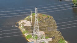
The three 230-kV circuits and one 69-kV circuit in question are in close proximity along a 1,300-ft (396-m)-wide stretch of the Alafia River. A variety of wood, steel and concrete structures supported the circuits to the north and south of the river, with steel lattice towers and tubular steel H-frames used to span the river itself. This included a set of structures on the tiny Key West Island, a spoil island in the river that reduced the longest span to about 1,000 ft (305 m). Adding to the project team's challenges, the island was sinking into the river.
Project Requirements and Goals
The initial driver for this project — to address corrosion-related structural deficiencies at the river crossings and eliminate their threat to reliability — soon gave way to other considerations: How could Tampa Electric use this opportunity to provide the best value and performance for its customers and shareholders? The utility assembled a project team to develop options, perform analysis and provide a recommendation to management.
In addition to the previously cited challenges, the geography of the project area proved to be extremely important. The Alafia River is an environmentally sensitive area and a popular recreational waterway. To the east and west, nearby bridges limit horizontal and vertical clearances. Tampa Electric made it a priority to minimize the project's impact on the environment and local community.
The utility had to consider other factors including future system upgrades and access to the project site for large equipment and many workers, both during the initial construction and later for possible restoration activity, while, at the same time, balancing its construction plan with project costs and the long-term life of the replacement structures. Above all, ensuring safety, the utility's highest core value, was a must for the project team and the public alike.
The project team was charged with developing a solution that would restore the structural integrity of the crossing structures and address the additional considerations in the most cost-effective manner. And the project had to be in service before the start of the 2011 hurricane season on June 11.
Project Development and Selection
The project team developed two options for completing the work. The first option called for remediation of the deficient structures with only limited new construction. The second option required much more new construction and included transmission structures that varied significantly in scale and potential benefits.
Because the corrosion-caused structural deficiencies initially were identified through a visual inspection, the project team commissioned CG Power Solutions to perform a comprehensive remediation study. CG inspected and tested the aboveground steel and reinforced-concrete foundations. Initial results showed only surface corrosion on the majority of the aboveground steel. However, the inspection revealed severe deficiencies in the steel connections to the concrete foundations, so much so that Tampa Electric added temporary reinforcement to one lattice tower on the spoil island based on CG's findings. The foundation testing showed the reinforced-concrete foundations on two of the lattice towers would not support any future Tampa Electric system expansion plans.
CG provided recommendations for remediating the foundations. An array of helical anchors would be suitable for some structures, but others would require more extensive remediation with supplemental concrete foundations.
In parallel with the remediation study, the project team developed conceptual designs for rebuilding the circuit crossings. The designs ranged from versions that maintained the existing configuration with in-place structure replacements to others that completely reconfigured the circuits and structures that would span the full width of the river.
The Best Solution
The team developed multiple options and evaluated each based on the project requirements. In an added wrinkle, the team factored in a fourth 230-kV circuit that would have to cross the river, part of a separate project and a new opportunity that came out of the multiple options the team had identified initially.
Using the recommendations and remediation estimate CG provided and the rebuild design options Tampa Electric developed, the project team narrowed the options to three and compiled separate cost estimates with scopes and schedules. Option 1 included remediation of the existing structures and limited new construction to accommodate the new circuit. Option 2 included replacement structures installed on the spoil island and new construction to accommodate the new circuit. Option 3 included new structures installed that spanned the river as well as provisions for the new circuit, and made possible the removal of the structures from the spoil island.
The project team determined option 3 would minimize the impact on the environment. Although temporary impacts to the island were necessary to remove the existing structures, this option would eliminate the significant excavation required for remediation and new installations. Option 3 also offered an aesthetic benefit by presenting a cleaner appearance along the river and a safety benefit by removing the structures from the spoil island, which is accessible to the public.
Removal of the existing structures and avoiding new construction on the spoil island provided short- and long-term benefits to crew safety, mobilization requirements, reliability, restoration and life-cycle costs. It also offered the opportunity to perform the engineering and design specific to accommodate the new circuit, and with minimal additional cost, the crossings could be built to handle significantly higher current levels if the circuits ever required upgrading.
With option 3, the project team had the best solution, one that met the minimum requirements at the least initial cost. It also offered many advantages that substantially addressed the other factors considered in this project. The team presented its findings, cost estimates, scopes, schedules and final recommendation to management and the project was approved. Now the hard work could begin.
Innovations and Project Complexity
This project broke new ground for Tampa Electric in three specific areas: structure size and span length; use and strategic deployment of lightning arresters; and implementation of a unique conductor tensioning procedure.
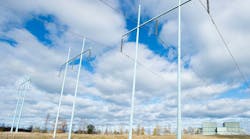
The crossing structures are the tallest, deepest and strongest, and have the largest diameter of any in Tampa Electric's transmission system. The spans across the river also are the longest in the utility's system. The Thomas & Betts tubular steel monopoles are 220 ft (67 m) in overall length, 8 ft (2.4 m) in diameter at the base with a 45-ft (13.7-m) direct-embedded depth and concrete backfill. The groundline capacity is in excess of 15,000 ft-kips (20,300 m-kN) and meets National Electrical Safety Code extreme wind requirements with all wires down in one direction. The river-crossing spans are more than 1,600 ft (488 m).
Although lightning arresters are standard equipment at Tampa Electric's substations and on the distribution system, their use on the transmission system has been limited and never above 69 kV. This project, however, includes two methods of lightning protection. Standard Tampa Electric transmission construction includes shielding with a static wire. But, since there can be as much as 60 ft (18.3 m) between the static wire and bottom phase conductor bundle, ABB lightning arresters were strategically incorporated into the design.
For protection from direct lightning strikes, lightning arresters on all three phases of the two outside circuits complement the standard static wires over the circuits. This provides an umbrella to the crossing spans and, because of their close proximity, should provide protection from direct strikes to the three inner circuits, as well. In addition, lightning arresters on the bottom phases of the three inner circuits to protect against back flashover. By eliminating the top- and middle-phase lightning arresters from the interior circuits, the project team cut more than US$20,000 from the project cost.
Sag-Tension Issues
Generation of sag-tension information is a simple process in the office. Recreating it in the field can be a greater challenge, especially for self-supporting dead-end structures. Further complicating things on this project was the fact the design called for bundled 795 aluminum conductor steel supported (ACSS) over the river to be backed up with a single 1590 ACSS away from the river. Tampa Electric used Power Line Systems' PLS-CADD to design the project and generate sag charts, but it was the capability of PLS that accurately predicted pole deflection, which was the basis for implementing a unique but effective tensioning procedure.
Historically, this has been a two-step process. First, crews would install the conductor in one direction at a point close to the specified tension. The second step involved the installation of the conductor in another direction and pulled up close to the specified tension. This is where operations became problematic and the frustration of tightening one side and loosening the other began. After lengthy discussions, the project team developed a new approach by leveraging the capabilities of PLS.
The new approach began with the design of a PLS weather case using measurements of typical conductor temperature, ambient temperature and wind speed at the project site during construction. This typical weather case was used with a deflection load case to analyze the self-supporting dead-end crossing structures under two scenarios that mirrored the standard two-step procedure. The first analysis determined the structure deflection at each attachment point with only the bundled 795 ACSS conductor and river-crossing static wire installed at full tension. These values were recorded. The second analysis determined the structure deflection at each attachment point with the bundled 795 ACSS conductors, the single 1590 ACSS conductors and static wires in both directions installed at full tension. These values also were recorded.
PLS predicted the structure deflection at the middle phase attachment point would be 40 inches (1,016 mm) under the first scenario, but only 16 inches (406 mm) under the second. This means the middle-phase attachment point would change positions by 24 inches (610 mm) — the result of 40 minus 16 (1,016 minus 406) — between the crew's first and second steps. Likewise, the static wire attachment would change by 35 inches (889 mm), the top phase by 30 inches (762 mm) and the bottom phase by 22 inches (559 mm).
In the field, the crew completed the first step by installing the 795 ACSS conductor and static wire to full tension over the river. As an interim step unique to this project, crews released the static wire and conductors by the differential amounts described previously. Crews then completed the standard second step of the installation procedure, the installation and full tensioning of the 1590 ACSS conductors and static wire. With the upland conductors at full tension, the tension in the river-crossing conductors was verified and required virtually no adjustments.
Achievements
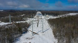
With high stakes, a tight time frame and processes the project team had to create along the way, the project achieved all of its goals. In late May 2011, before hurricane season, Tampa Electric rebuilt the four existing circuit crossings and constructed the new circuit crossing at the Alafia River. The project solved the problems of structural deficiencies and offered a clean installation with major operational and maintenance advantages. The environmental impact was temporary and finite because all equipment was removed from the spoil island.
The final configuration accommodates the new circuit, offers a current rating of 1,000 A more than the previous rating and creates enough room for another circuit crossing in the future. In the end, the project required more than 8,800 man-hours for construction and came in almost 10% under the $5.5 million project estimate. The project earned Tampa Electric the 2012 Industry Excellence Award in the transmission line category from the Southeastern Electric Exchange and is one the utility will return to as a model of safe, large-scale achievement for many years to come.
Acknowledgement
The authors acknowledge the other members of the project team: Chuck Rogers, Ed Fridy, Nate Alcoz, Chris Steele, Dave Johnson and Matt LaRussa. They also thank Suzette Knight, Glenda VanPetten, Marcie Collins, Nicki Narloch and Carla Hunt. Without the handful of miracles they performed, this project would have been over-budget and missed the in-service date. Finally, the authors thank Cherie Jacobs and Brian Lott for their significant contributions to this article.
Phillip Hughes II ([email protected]) has 16 years of experience in the electric power industry, with 11 years at Tampa Electric Co. He has eight years of transmission operations and engineering experience and currently is a senior consulting engineer responsible for new construction projects, system modifications and resolution of LiDAR clearance issues. Hughes holds BSME and BSEE degrees from the University of South Florida and is a professional engineer registered in Florida.
Kenji Plennert ([email protected]) is a senior engineer at Tampa Electric Co. and has 10 years experience in the electric utility industry. He previously worked in Tampa Electric's transmission engineering group for five years and recently transferred to the position of distribution operations engineer. Plennert holds a BSME degree and a MBA degree from the University of South Florida.
|
Companies mentioned: ABB | www.abb.com AFL | www.globalafl.com CG Power Solutions | www.cgglobal.com NGK Insulators | ww.ngk.co.jp Power Line Systems | www.powerlinesystems.com Southeastern Electric Exchange | www.theexchange.org Tampa Electric | www.tampaelectric.com Thomas & Betts | www.tnb.com |


