PECO recently completed the installation of a second transmission line to serve its Clay Substation, located in a remote section of rural Chester County, Pennsylvania, U.S. The goal of this work was to improve overall system capacity and reliability for the area. The work required a 25-day outage that completely shut down the existing transmission line to Clay Substation. De-energizing the transmission did not impact the customers as PECO was able to reroute more than 50 distribution circuits serving 35,000 customers so that they did not lose service when the Jennersville Substation was de-energized.
Preparations for the Project
As with any large engineering project, PECO's Clay project required a significant amount of engineering and design work to ensure electric customers would not be impacted adversely by this work. The construction project schedule called for substation outages to last for nearly one month, so short-term solutions would not be adequate. PECO's capacity planning engineers built detailed system models in the utility's CYME Power Engineering application to identify any local problems, such as abnormal or out-of-tariff voltages, cogeneration impacts, fault current contributions and phase-balancing issues. While CYME has been used extensively at PECO, this was the first time it had undertaken such a comprehensive model as part of a single effort.

The initial analysis results recommended several phase-balancing opportunities as well as capacitor installations. It also indicated PECO would need to install temporary generation to provide voltage support for key areas. The focus of the analysis team then shifted to determine strategic locations for temporary generation and the amount needed.
Ultimately, the team targeted four locations for temporary generation. PECO prepared the proposed sites for use by building new terminal poles and modifying the protective relaying schemas to account for the new voltage sources.
AMI Role
Meanwhile, as that work was underway, PECO also was actively deploying its Smart Grid Greater Philadelphia project, which includes a systemwide communications network and new advanced metering infrastructure (AMI). By design, the communications network had already been installed in the Clay Substation area. The communications infrastructure included the installation of fiber-optic synchronous optical networking (SONET) communications rings, WiMAX wireless broadband communications for remote data backhaul, and the Sensus FlexNet network for direct meter communication and distribution automation (DA) devices. The AMI deployments also were underway in other PECO regions.
During the routine engineering design challenge sessions, it was asked whether PECO could use the voltage-monitoring capabilities of the AMI meters to track customer voltages in areas of concern surrounding the Clay project. While the AMI meters are capable of such monitoring, initially they were not scheduled to be installed in the surrounding Clay Substation area until months after the project was to have been completed. Furthermore, the various applications to deliver and analyze voltage data had not yet been developed.

A request was made for the smart grid team to determine whether a group of select AMI meters could be installed in advance to support the Clay project work. Since the FlexNet network was already in place, and PECO was already installing electric meters in other parts of its system, it was indeed possible to install meters for this purpose. More than 150 key metering locations were selected for voltage monitoring. Additional work was needed to provide a means to retrieve the voltage data from the AMI system and deliver it to the engineering groups for analysis.
The smart grid IT resources were fully committed at the time, delivering the basic system functionality and billing capabilities. PECO turned to Sensus to develop a temporary solution to meet the project needs. Sensus was able to provide a daily voltage profile data set for each meter in the project area. This data set provided hourly minimum, maximum and average voltage readings for the previous 24-hour period.
The select AMI meters were installed several weeks prior to construction and circuit reconfiguration was scheduled so as to provide baseline data. The initial data indicated the customer voltages were well within the specified tariff guidelines of ±5% V (114 V to 126 V for a 120-V service). In many locations, the system was found to be operating on the mid to upper portion of the tariff range because of mild springtime weather and light system load conditions.
Construction and Voltage Monitoring Starts
Actual circuit switching began in April 2012. The initial daily voltage reports indicated slight changes in overall customer profiles, but the voltages were still well within the tariff limits. In many cases, the actual voltages were higher than the engineering studies predicted. This was welcomed news, as the standby generation did not need to be used. This trend continued as 50 distribution circuits were reconfigured. A daily voltage profile was issued from the AMI system.
PECO's meters sampled the delivered voltage every second and recorded the hourly average, absolute minimum and absolute maximum for each premise. Certain preprogrammed voltage thresholds also were defined to trigger automated alarms indicating brownout, low-voltage and flickering conditions. The daily voltage data helped to identify specific locations where momentary voltage anomalies were occurring. Subsequently, the engineering team identified a couple of issues where capacitor banks were operating with incorrect settings and locations of significant customer load growth, which led to further modeling.
Significant Benefits
The transmission line construction proceeded smoothly until the critical substation work was complete and the stations could be re-energized. Throughout the field work phase, the select AMI meters provided data to supplement existing substation voltage measurements. The combined data provided the means for the system operations to defer activating standby generation. The avoided operating and fuel costs were estimated to be in excess of US$1 million.
The AMI voltage data collection continued for several additional weeks following construction completion to ensure there were no adverse customer impacts. This data, combined with the extensive modeling, has provided a great opportunity to compare real-life scenarios to a static distribution model. The loads on each circuit in the model were quite close to the loads that occurred in the field, but the voltage characteristics were slightly lower in the model than the voltages seen in the field. Future engineering work will strive to hone the modeling practice and include sources of field data earlier in the design process. With more AMI meters being deployed, the possibility exists to make fewer initial modeling assumptions and easily validate models with AMI data.
Reporting of voltage data was conducted with simple off-the-shelf database tools already available to engineering teams. Because of the geospatial nature of the meter data, additional reporting was performed to assemble geographic information system (GIS) reports, or maps, of the voltage data. When overlaid with circuit topologies, this data provided clear visualizations of voltage drop, locations of high load and customer density. Once an entire area has completed with the AMI deployment, the amount of data available to shade a map or fuel a GIS report will be sufficient to visualize the distribution system as a living machine.
Smarter Grid, Smarter Operations
From an AMI and smart grid perspective, the Clay project has provided a real-world field test of how AMI data can be used to enhance distribution system design and operations. PECO and others will continue to refine this process as AMI and distribution operations converge on today's modern grid. Sample benefits include full-scale delivery-point voltage monitoring, power-quality programs, reliability programs and analytics, and volt/VAR management programs, including conservation voltage reduction programs.

While this phase of the project is now complete, more work is planned to complete the conversion of the Clay Substation from a single transformer/single distribution bus configuration to a duplex substation configuration by adding a second bulk-power transformer, installing new primary and secondary tie buses, and upgrading distribution feeder bays. Also, the substation's existing analog protection and supervisory control and data acquisition equipment will be replaced with new modern protection equipment.
Acknowledgment
As with most projects, this too was a team effort. The author wishes to acknowledge PECO's engineering and project management teams for their dedication to this effort. William Hicks was particularly instrumental in getting the project done and has helped with graphics preparation for this article.
Glenn Pritchard ([email protected]) is the smart grid network operations and technology lead for PECO's smart grid/smart meter project. Pritchard graduated from Clemson University in 1990 with a BSEE degree. He is a registered professional engineer in Pennsylvania and has been with PECO for 20 years, and is responsible for developing new applications that leverage the smart grid, AMI systems and metering data.
C. William Hicks, IV ([email protected]) is a co-operative employee from Drexel University who is with the PECO Smart Grid/Smart Meter project. Prior to this assignment, Bill worked with PECO in electrical distribution and transmission planning. He is a student member of the National Society of Professional Engineers (NSPE) and the Institute of Electrical and Electronics Engineers (IEEE) and is anticipating graduation in 2013 with a BSEE (Power).
The Clay Project
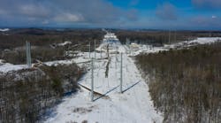
The Clay Project upgraded an existing 230-kV transmission line and added a new 230-kV line on 7 miles (11 km) of the existing line route. This complex project, which improved overall system capacity and reliability, included the following:
- Installation of 39 dual-circuit monopole structures
- Temporary transfer of existing line to new towers
- Removal of existing lattice towers
- Reconductoring of a significant portion of the line.
Materials for the project included:
- 39 monopole structures
- 225,000 ft (68,580 m) of primary conductor
- Insulator suspensions, stacks and associated hardware.
The foundations and bottom sections of the monopoles were constructed while the line was energized. During the outage, the top sections of the monopoles were installed and the conductor transferred from the lattice structure to the new double-circuit monopoles. When complete, the remaining portions of the lattice towers were removed.

Additional activities included several substation upgrades such as installation of new line, transfer trip relay protection over an OPGW fiber communications path, and removal of the existing analog protection panel, power line communication equipment and wave traps) There also were upgrades to transmission and substation energy management system, supervisory control and data acquisition.
Companies mentioned:
CYME | www.cyme.com
PECO | www.peco.com
Sensus | www.sensus.com