Today's emphasis on implementing energy-efficiency programs and limiting peak demand growth is driving renewed interest in an effective method of implementing volt/var control on distribution systems: conservation voltage reduction (CVR). In CVR, the system demand is reduced through controlled reduction in operating voltage at customer load points.
Model-based volt/var optimization (VVO) utilizes a dynamic operating model of the distribution system, in conjunction with a rigorous mathematical optimization algorithm, to achieve a given operating objective. It is typically based on a distribution connectivity model, as found in an organization's geographic information system (GIS). The operating status of the components in the system model is usually changed by direct operator action in the control room or via a SCADA interface. The SCADA delivers changes in the status of system components, such as distribution breakers, switches, reclosers, fuses, jumpers and line cuts.
The benefit of utilizing a dynamic model is that the volt/var optimization is always dealing with the "as-operated" network state. This ensures that the determination of the voltage regulator taps, load tap changer (LTC) taps and switched capacitor states always reflects the present operating configuration of the system.
The savings made by deferred generation expansion, reduced capacity procurement, lowered system losses, decreased customer energy consumption and reduced operating and maintenance costs provide a very strong business case for model-based VVO in smart grids.
Due to their inherent technology limitations, previous volt/var control methods – namely local-based controls and one-way centralized radio-controlled systems – did not permit systematic optimization of voltage and var controls for maximum effectiveness in terms of loss reduction and CVR demand. Legacy systems also required additional servers and communications infrastructure unsuitable for additional smart grid functionality such as fault location, self-healing restoration, and comprehensive distribution system monitoring and control.
With the commercialization of model-based volt/var optimization, and the extension of SCADA and intelligent electronic devices on the distribution system, distribution organizations are now able to achieve maximum performance benefits with reductions in demand and energy, real power losses and operating costs.
History
Since distribution systems were first developed in the late 1800s, a great deal of effort has been spent countering the impact of reactive power and voltage drop. Distribution line voltage regulators, load-tap changing transformers and switched and fixed capacitor banks were developed to help keep customer voltages within regulatory bandwidths, free up capacity in the generation, transmission and distribution systems, and reduce real power losses.
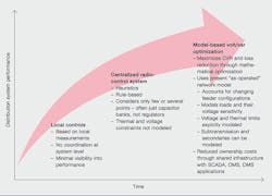
Local controls were the first control measures introduced. Applied to LTCs, line voltage regulators and switched shunt capacitor banks, they utilize measurements local to the device. These measurements include current and voltage, and, in the case of switched capacitor banks, sometimes indirect inputs such as time and temperature. These inputs are often used as a proxy for the actual reactive current flow ➔ 1.
1 The major developments in volt/var control
With local control, there is no explicit centralized coordination of volt/var devices at the system level, and implementation of CVR is far from optimal. In addition, there are costs for field personnel to travel to a site to check for things such as blown fuses, to verify controls are operational, or to change control settings to match the seasonal load.
If banks are not operational, or even if they are operational but with the wrong settings, the voltage may be unacceptable and the power factor will be less than ideal most of time. This also occurs when time or temperature settings are not well correlated with the actual reactive current on the feeder during given days or seasons. This creates additional real power losses caused by excessive reactive current flow.
Centralized radio control was introduced about 30 years ago. This utilizes a central monitoring system, often based on heuristics, utilizing only the var measurement at the distribution feeder breaker. Simple one-way communication with switched capacitor banks, for example, is typically employed. Often the only quantity that is monitored is the var flow at the feeder breaker. If the distribution feeders are reconfigured due to normal switching, load balancing or fault isolation, the rules-based logic is not able to automatically track the capacitor banks on the presently connected feeders. The lack of visibility, predictability and optimization across the system made CVR implementation impractical. Therefore, distribution companies have advanced to model-based VVO methods.
The Increase of distribution models in system operations
Computerized distribution system models have been used in distribution planning for decades. They have been used to facilitate distribution system planning and design, and study system modifications such as line extensions, reconductoring, substation and feeder additions, voltage uprates, sectionalizing devices, shunt capacitors and voltage regulators.
Back in the early 1990s, the distribution models started to be used more often in the operations environment. Namely, model-based outage management systems were developed for use in distribution control rooms. System connectivity, the location of protective and switching devices, and the location of customers permitted more accurate outage prediction engines. Shorter customer outage times and more efficient use of field crews were the result.
Initially, the electrical characteristics, such as equipment impedances, ratings, and loads, were not used in the distribution operations system model. This was for several reasons: First, the effort required to maintain and use such data in an operations environment was judged to be greater than the operational benefits gained. A distribution system model is different from the transmission model that most operations used in SCADA and/or Energy Management Systems (EMSs). The distribution system is much larger, 10 to 20 times, typically, and the system model must be a per-phase, unbalanced model to accurately calculate distribution conditions. Second, distribution system applications, such as fault location, volt/var optimization and self-healing had not been developed to leverage the distribution models in the operations environment.
Today, there are a number of factors driving the use of electrical models in the operations environment. Business drivers include demand reduction, energy efficiency, improved asset utilization and improved distribution situational awareness. Technical drivers include improved availability of computational power for handling large distribution models, more companies with a complete GIS model of their distribution system, the addition of cost-effective sensoring, intelligent devices and communications that can be used with the distribution system model and the development of advanced distribution applications such as volt/var optimization.
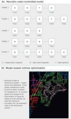
2 Heuristic radio-controlled model versus model-based volt/var optimization
Model-based volt/var optimization
Model-based volt/var optimization has many advantages over local-control-based methods and centralized radio-controlled schemes ➔ 2. Foremost among these is that the as-operated state of the system, including near real-time updates from SCADA and outage management systems (OMSs), is used. This enables distribution companies to maintain the precise voltage control needed to implement CVR without violating customer voltage limits. Model-based systems are able to consider changes to the network as they occur, including load and capacitor bank transfers between feeders, and changing load conditions.
Past heuristic methods, such as monitoring power factor at the feeder breaker, are not optimal solutions. There can be tens of km (or miles) of conductors on a feeder. It is the voltage and var flow throughout the entire feeder, and not just at the feeder breaker or several other points, that impact the losses and demand on the feeder. A three-phase, unbalanced load-flow model-based solution results in a more accurate volt/var strategy than heuristics.
The technology required to support VVO, including GIS-based network models, two-way communications to distribution substations and line equipment, and IT resources, is now commonplace.
Model-based VVO will also enable distribution organizations to accommodate new complexities: increased renewable generation located at distribution voltage levels; more automated fault location and restoration switching schemes; increased system monitoring and asset management processes; and expansions in electric vehicle charging infrastructure.
How it works
Simply put, the model-based VVO application is used to optimize an objective function subject to a set of nonlinear equality and inequality constraints, including thousands of equations for unbalanced load flow with several thousand state variables. The nonlinear, non-convex combinatorial properties of the model-based VVO problem, coupled with high dimensionality (a large number of state variables) explain why model-based VVO has been a longstanding challenge in the industry.
The model-based VVO algorithm can be summarized as follows: Minimize real power losses and/or real power load, subject to the following engineering constraints:
- Power flow equations (multiphase, multiscore, unbalanced, meshed system)
- Voltage constraints (phase-to-neutral or phase-to-phase)
- Current constraints (cables, overhead lines, transformers, neutral, grounding resistance)
- Tap-change constraints (operation range)
- Shunt capacitor change constraints (operation frequency)
Using the optimization control variables:
- Switchable shunts (ganged or unganged)
- Controllable taps of transformer/voltage regulators (ganged or unganged)
Model-based VVO uses unbalanced load flow (UBLF) and load allocation (LA) applications to obtain the starting network state. It also invokes UBLF to provide sensitivity (gradient) factors, obtain intermediate solutions in the voltage control iterations and check the feasibility of candidate solutions. The UBLF application is required, as opposed to a balanced load flow application, due to the numerous single- phase loads typically found on a distribution system, as well as single-phase laterals that can have controllable regulators and capacitors.
The common three-phase, unbalanced distribution model used by model-based VVO can accommodate all common transformer connection configurations, ungrounded or weakly grounded networks and any degree of meshing.
For accuracy, a detailed network model is used. Phase-based models are used to represent every network component. Loads or capacitor banks can be delta or wye-connected. Transformers can be connected in various delta/wye and secondary leading/lagging configurations with or without ground resistance and with primary or secondary regulation capability ➔ 3.
Both voltage and var controls can be ganged or unganged. The method works on radial as well as meshed networks, and with single or multiple power sources. Voltage controls are enforced for each individual phase, using phase-to-ground or phase-to-phase voltage, depending on the connection type of the load. Any regulators or capacitor banks that are temporarily disabled due to maintenance or operational issues can be temporarily excluded from the analysis.
Model-based VVO considers the voltage- dependent component of loads in order to model the reduction in demand versus the reduction in voltage. The optimum settings for each regulator or LTC depend on the mix of constant power and constant impedance loads on the distribution circuit.
Integration with other smart grid functionality
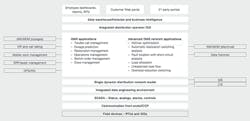
Once implemented, the infrastructure and resources that are needed for model-based VVO – including the network model, SCADA, communications and the server/ hardware infrastructure – can be leveraged to provide additional distribution management system (DMS) functionality, such as self-healing (automated restoration switching analysis), unbalanced load flow, fault location and overload reduction switching. Furthermore, integration of the DMS applications with other utility enterprise systems (eg, demand response management systems, business intelligence applications and OMSs) can deliver additional value ➔ 4.
4 VVO in an integrated distribution operations platform
In addition, operators and utility enterprise systems can benefit from better situational and operational intelligence. Knowing, through the graphical maps and tabular displays in the DMS, the status of volt/var equipment along an as-operated feeder improves operator awareness. Model-based volt/var applications can also leverage SCADA/DMS alarms for failed Field-based controllers, blown capacitor fuses and failed regulators or capacitor banks. This and other information can be fed to asset management and mobile workforce management systems. The loss and demand reduction data can be supplied to systems that evaluate savings arising from reduced fuel costs for a generating utility and reduced power purchase costs for nongenerating utilities.
Advantages
Model-based VVO now allows distribution companies to implement voltage and var optimization under real-world conditions and with numerous advantages over previous methods:
- The mathematical optimum is computed, instead of a rule-based heuristic solution.
- Maximum reduction in power and energy losses, customer demand reduction and freed-up capacity is determined using a mixed-integer, nonlinear programming method.
- Operating objectives can be changed to meet business requirements.
- The optimization can be set to execute on a defined schedule, or when there are significant system changes.
- Offline simulations can be performed, allowing different system configurations and contingencies to be studied.
The as-operated state of the network is utilized by the optimization.
- As outages and system reconfigurations occur, the network maintains proper connectivity of loads, capacitor banks, regulators and other feeder components.
- The network model is kept up to date incrementally as part of the outage and distribution updating process.
- With one common as-operated network model for all smart grid applications to draw from, consistency is guaranteed.
Infrastructure and maintenance costs for implementing multiple DMS applications are reduced.
- Model-based VVO utilizes the same resources as SCADA, OMS and other DMS applications.
- With integrated DMS, there is no duplication of computing infrastructure and communications environments for implementing other smart grid applications.
- Having a single DMS distribution network model eliminates synchronization issues between different models maintained in different applications.
A three-phase unbalanced network model is utilized.
- A detailed, unbalanced three-phase system model improves accuracy.
- Multiple voltage levels can be modeled, including subtransmission and secondary voltage levels.
- Networked and looped systems can be included, not just radial.
- The impact on the entire network model is calculated.
- Voltage imbalance is included, as are ganged and unganged controls.
Customer loads are modeled explicitly.
- A voltage-dependent representation of customer loads is used since they differ with how load varies as a function of voltage and differ in reactive power requirements.
- The location, size and type of loads on the system determine the optimal LTC and regulator settings for CVR.
- Voltage at load points is calculated and compared with operating limits.
- Customer loads can be represented as a function of time.
Model-based VVO: the future
Model-based VVO is perfectly attuned to other advances in distribution systems. For example, the increased use of automatic fault location and automated switching and restoration schemes uses the same model. These applications reconfigure the distribution system, changing the location of loads as well as the location of voltage regulators and capacitor banks. Older-generation, rule-based volt/var methods were not able to account for such system changes, whereas model-based VVO can. Indeed, it can do so explicitly and automatically.
Further, model-based VVO helps organizations deal with growing numbers of renewable energy generators. Distribution organizations are already experiencing the voltage fluctuations caused by distribution-connected renewable generation, especially from single-phase residential photovoltaic systems. Model-based VVO already models multiple generation sources and it can be adapted to model and control reactive power from renewable sources.
As advanced meters and cost-effective remote voltage-sensing devices continue to be deployed at load points in ever greater numbers, additional end-point voltage readings will become available to the optimization routines. This additional information will further enhance the performance of the model.
Tim Taylor
Ventyx, an ABB company
Raleigh-Durham, NC, United States
[email protected]


