The need for a new policy on spare extra-high-voltage (EHV) transformers emerged in 2011 when Statnett, the Norwegian transmission system operator (TSO), commenced a huge investment and reinvestment program. New renewables in the form of wind farms and a large number of small-scale hydro power plants were being connected to the TSO’s 300-kV transmission system in areas with surplus energy. The energy had to be either transmitted to areas in Norway with an energy deficit or, alternatively, exported to other countries.
Major system failures around the world have been attributed to transformer failures. This critical issue was foundational to creating awareness on Statnett’s board of directors of the need for good contingency planning, including investing in spare parts such as system transformers. Prior to 2011, the TSO held no dedicated spare EHV transformers in storage. Even though almost all its EHV substations fulfilled the N-1 design standard for system security, Statnett considered the risk to be underrated that a second transformer in a two-transformer substation could fail as a result of the same fault cause as the first transformer.
Risk Assessment
As a result of its board’s concern, Statnett performed risk assessment studies. The starting point for these studies was an evaluation of the transformer’s criticality in the substation. The monetary value of energy not served was calculated using the Norwegian energy regulators’ scheme of quality adjustment for energy not served, based on an evaluation of the different customer groups as performed by SINTEF Energy Research.
The following was the basis for the probability analysis:
• The operational policy of Statnett specifies a maximum power outage of 200 MW and a restoration time of one hour maximum.
• In the event a transformer failure causes an energy not served status to last more than two hours, a spare transformer is needed. This is normally covered by overloading the neighboring unit in the bulk substation.
• The maximum installation time for a spare transformer is four weeks.
• The estimated maximum repair time for a faulted transformer is one year, but the average repair time is six months.
• A minimum of one spare transformer must be installed if a long-term outage occurs.
• The Statnett transformer failure rate for serious failures based on a 10-year average in 2011 was 0.4%, or four failures per 1,000 transformer years, compared with the transformer failure rate of 0.32% published by CIGRE.
• Because of a considerable uncertainty margin in the failure statistics, the analysis was performed for both 0.3% and 1% failure probability.
Failure Implications
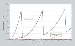
With a population of 10 transformers and one spare unit, if there is a failure rate of 1% and it take six months to reestablish the required transformer capacity, the probability of a second failure without an available spare unit is 0.25%. Therefore, the average return time for such an event would be 400 years.
If this risk is considered the upper limit for acceptable risk, it is necessary to increase the number of spare units from one to two when the population of similar transformers is 11 units. Furthermore, on this basis, the number of spare units must be increased to three when the population exceeds 27 transformers and to four when the population exceeds 45 transformers. These results are calculated as independent failures, which is not always the case if the transmission system contains several transformers of the same design, age and manufacturer.
It should be noted the average failure probability, average time to reestablish the required transformer capacity in the event of a failure and variation of these parameters highly influence the results. Experience also shows that top management risk aversion is highly dependent on when the last outage resulting in energy not served occurred.
Spare Transformer Standards
Statnett has established standards for dedicated spare transformers outside the N-1 system security standard in each EHV substation:
• The spare transformer shall be stored de-energized, oil-filled with accessories assembled on the transformer or in dedicated storage containers. This avoids the need for costly transformer bays, switchgear and protection equipment.
• Each stored transformer must be registered separately in the enterprise resource planning system with detailed technical, contingency and environmental parameters.
• When several spare transformers are stored in the same geographical location, a risk and security analysis must be performed to evaluate the risk for unwanted events that may involve several of the stored units.
• A spare 300-kV transformer is normally designed for connection to the 420-kV transmission system (reconnection through access to the main windings to change the position of links).
• For transformer low-voltage levels of 69 kV, the reconnection to 138 kV is always required to cover a future voltage upgrade of the customer’s grid. The anticipated long-term solution is to upgrade 33-kV, 50-kV and 66-kV grids to 132 kV.
• Both the 300-kV and 420-kV grids are solidly grounded. All 33-kV, 66-kV and 132-kV grids in Norway are grounded by high-impedance earth fault reactors (Petersen coils), except the 132-kV grids in and around the cities of Oslo and Bergen, which are both low-impedance grounded grids with some neutrals solidly grounded and others grounded through a 60/45-Ω reactor.
Statnett’s Spares
The following spare transformers units have been procured since Statnett introduced its policy in 2012:
• Spare 1: Delivered in 2013, this 420-300/138-69-kV, 250-MVA transformer has an on-load tap changer (±16 × 1.4%) and a transport weight of 185 metric tons.
• Spare 2: Delivered in 2013, this 420-300/138-69-kV, 160-MVA transformer has an on-load tap-changer (±16 × 1.4%) and a transport weight of 150 metric tons.
• Spare 3: Delivered in 2014, this 420-300/50-kV, 160-MVA transformer has an on-load tap-changer (±12 × 1.4%) and an installed weight of 225 metric tons. This unit is a spare for 16 transformers. Statnett has another spare for this voltage ratio and MVA rating to fulfil the spare number requirements.
• Spare 4: To be delivered in 2015, this 420-300/138/47-kV, 300-MVA transformer has a transport weight of 250 metric tons. This unit is a spare for five transformers in four bulk supply substations where the capacity on the customer’s 132-kV cable grid is limited, so the neighboring substations cannot take over the full load.
The price for these four dedicated spare transformers is 9.2 million euros (US$10.5 million), excluding Statnett’s follow-up costs and transportation from the Netherlands to Norway for installation in the warehouse.
The Spare 1 and Spare 2 units cover a combined population of 76 transformers and further spares are envisaged. Both of these transformers have two sets of bushings, one set for 420 kV and another for 300 kV, and each set includes one spare bushing. This is a result of the small size and limited height in some of the transformer bays in the 300-kV substations.
The Spare 3 unit had to be specified with a maximum installed weight. The transport plans did not limit the weight, but it was necessary to avoid calculating the civil design at the 16 existing transformer bays (for the voltage ratio 300/50 kV) to check them for the new maximum installed weight.
The Spare 3 unit’s specification also included a minimum longtime overload capability of 1.5 per unit (p.u.) at 0°C (32°F) ambient air temperature. Hence, a higher hot-spot winding temperature was allowed with a rise of +90K, or a hot-spot reference temperature of 110ºC (230°F). This is higher than the hot-spot winding temperature rise of +78K, or a hot-spot reference temperature of 98ºC (208°F), specified for standard Statnett transformers. The design review showed the increased hot-spot temperature was not needed and a long-term overload at 1.65 p.u. is possible at 0°C ambient air temperature. This makes the third spare rather useful in an emergency.
The Spare 3 transformer also is designed to accommodate three different locations for the oil conservator:
• On the transformer is the standard solution
• On the wall with piping to the transformer main tank
• On separate support consoles to the floor.
These three configurations are in use on the 16 units where the Spare 3 unit may be required.
The increased overload current has to be checked for bus bars and switchgear in each substation. The protection relay plan also has to be changed as Statnett regularly trips transformers at 1.4 p.u. and at low temperatures, with a top-oil temperature trip at 95°C (203°F) and winding temperature trip at 115°C (239°F). When required, these settings are easy to change on the transformer winding temperature indicator and oil temperature indicator.
For all Statnett transformers, the manufacturer’s heat-run test specified has been upgraded with the introduction of a 130% overload during the first six to eight hours. The installed fibre-optic sensors enable the real-time hot-spot and oil temperatures to be checked. The results from this upgraded heat run are of particular interest to Statnett’s operations division because the test provides the real temperatures at overloading.
To facilitate a sweep frequency response analysis (SFRA) measurement during the factory acceptance tests, and also when the bushings are not installed because the transformer is a cold spare, a set of 1-kV test bushings is located on all bushing transport covers on the tank, and the winding leads are connected to the test bushing and grounded there. Two full sets of SFRA measurements are performed during factory acceptance tests, with the bushings installed and with the test bushings installed, but the latter without oil. Hence, a set SFRA measurement will be taken in the transformer warehouse in Norway before the tank is filled with oil.
These measurements will be the template for future measurements when the spare transformer is moved to a substation to be installed for service.
Spare Storage
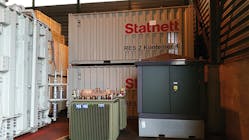
The four spare transformers are stored in a warehouse without the accessories but with the oil conservator installed and the main tank oil-filled. All the accessories, except the bushings and radiators, are stored in thermally insulated containers with heating, ventilation and humidity controlled fans to avoid condensation.
These containers are procured with the spare transformers. The containers have a detachable roof to enable lifting out the crates, and the galvanized containers are equipped with sockets for electricity and earthing lugs.
The conservator is located on the tank and is only filled with some oil as the temperature is quite stable in the warehouse. Oil-spill detection equipment will be installed and detection is identified by a signal from the Buchholz (no oil/high gas) to the load dispatch center. This system is considered better than installing oil sensors. An oil-resistant mat is located under the transformer and over a rim to contain any oil spill.
The spare transformers are stored on each side of the warehouse to allow the girder hanger to move in between the transformers.
Current Status
Following approval in 2012, Statnett procured four new spare transformers especially designed as spares. Statnett has rented a warehouse to keep these transformers indoors with their accessories partly in storage containers procured with the transformers. The TSO is currently considering establishing a permanent spare transformer warehouse.
Kjetil Ryen ([email protected]) works as an adviser for transformers at the Norwegian transmission system operator, Statnett. He earned a bachelor’s degree in electronics from Oslo Technical College in 1974 and a master’s degree in power engineering from the Norwegian Institute of Technology (now the Norwegian University of Science and Technology) in 1986. In 2004, he was elected to the grade of senior member in IEEE, and he is active in CIGRE.

