Several commonly used transmission line structure configurations have proven to be effective and efficient in providing the structural and electrical reliability essential to transmission owners. However, unique situations and circumstances sometimes require the development of a nontraditional structure configuration to meet the challenging objectives of a project.
In such cases, it is critical the engineer be familiar with all the structure designs developed for past projects. It is essential the engineer be knowledgeable about new technologies, willing to work with material suppliers and other design stakeholders to be creative, and open to new ideas. The combination of history, knowledge, exceptional engineering judgment and creativity will result in state-of-the-art designs that provide transmission owners with cost-effective solutions to deliver reliable transmission service.
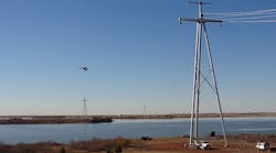
A recent project was developed for Oklahoma Gas & Electric Co. (OG&E) to construct a new single-circuit 345-kV transmission line in central Oklahoma, U.S. Because of physical, environmental and federal constraints, the only practical routing option required the transmission line alignment to cross Sooner Lake. Therefore, a specialized structure configuration would need to be developed to support the transmission line’s lake crossing.
Design Challenges
The engineering design team faced several challenges during the development of the lake crossing structures. First, the closest distance between shorelines was 1.2 miles (1.9 km); however, an island in the lake enabled a two-span crossing design, with each span at approximately 2,800 ft (853 m). Second, Federal Aviation Administration constraints and OG&E preferences dictated each structure be less than 200 ft (61 m) above ground line.
Additionally, OG&E engineering standards for crossing large bodies of water that are navigable and accessible to sailboats required at least 50 ft (15 m) of clearance be maintained to the surface of the water. This included the maximum water elevation and energized conductor at the maximum design sag condition.
Finally, OG&E did not possess a standard structure design that could accommodate the project requirements or project schedule, so a new tubular steel design was required. OG&E secured the services of Electrical Consultants Inc. (ECI) to work directly with Valmont–Newmark (Valmont). The goal was to develop an efficient and innovative structure design that would meet the needs of the project and provide reliable service for the life of the transmission line.
Wire in the Air
The development of the lake crossing began with the conductor design. The design team applied the same conductor and sagging criteria used for the majority of the project, which was based on the clearance requirements and project constraints. For the lake crossing, the required structure height was estimated to be approximately 275 ft (84 m). The design team then looked into developing a new conductor design that would allow the structure height to remain below the 200-ft (61-m) limitation.
Several conductor types were considered, including customary aluminum conductor steel-reinforced (ACSR), aluminum conductor steel-supported (ACSS) sizes and newer conductor types involving composite core technologies. Ultimately, the ECI design team worked directly with Southwire to develop a specialized ACSR-type conductor with the electrical, strength and performance properties that would meet the needs of the project. The shield wires were similarly designed to be compatible with the conductor sag throughout the range of operation and with each design load case.
Once the conductor, shield wire types and tensions were established for the lake crossing project, structural design and analysis were conducted. The process began by defining the load cases for each structure type. Determining the magnitudes of the point loads, developing preliminary structure designs and performing the analysis allowed comparisons to determine the most effective structure design.
The National Electrical Safety Code defines three specific load cases that must be considered, with the conditions and load factors included in each case; these served as the primary load cases for the structural design of the lake crossing structures. OG&E also established several other loading criteria based on weather events common in the area and the level of reliability required for the transmission line. These criteria included critical wind, extreme ice and uplift load cases. Once the load cases were established, specific properties of the transmission line crossing design were applied to determine the magnitudes of the loads for each load case.
Structure Types
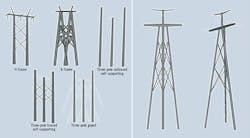
With the design loads defined, the engineering team focused on developing the structure configuration that would provide the most efficient and cost-effective solution for the lake crossing, while keeping constructability and maintainability a priority. Based on design data provided by ECI, Valmont developed preliminary designs for several conventional structure configurations.
The guyed structure was identified as the lowest-cost solution; however, OG&E preferred to use a self-supporting option. The A-frame and H-frame options were the next most effective designs, fairly similar in cost and performance. However, ECI decided a more efficient solution could be possible with a nontraditional structure configuration.
Experience and engineering principals dictate a triangle is a very stable geometric shape. Additionally, a compression-tension structural design typically requires smaller pole diameters and shallower foundations than bending moment structural designs. This was first observed with the analysis of the A-frame structure option. By incorporating a triangular shape into the design, an efficient and stable structure could be developed using a compression-tension load system rather than a bending moment system.
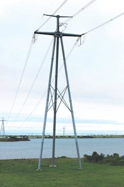
Based on this approach, the ECI engineering team developed an innovative tripod-type structure configuration as the solution. Preliminary designs indicated the tripod structure was 46% lighter than the next most efficient design. Once the preliminary structural analysis was performed, ECI completed a foundation analysis for each structure type so a total installed cost comparison could be made to select the most efficient and cost-effective option.
Using the preliminary shaft sizes and ground line reactions provided by Valmont, drilled concrete pier foundation designs were developed based on the criteria established for the project. The A-frame structure required the smallest foundation sizes, while the tripod structure required slightly larger foundations, as expected. However, the A-frame required four foundations, while the tripod structure, with its smaller overall volume of concrete and less installation labor, only required three foundations.
Tripod Innovations
Based on the results of the structural and foundation analyses, the tripod structure provided the most efficient and cost-effective solution, which is why it was selected for implementation. The Valmont engineering group then began working to refine the preliminary designs of each tripod structure further by detailing attachments and engineering the specific components of the structure.
A major challenge for the Valmont engineering group was designing the central member of the structure where the legs, arms and body members converge to a common structural member. This central point of the structure serves as the primary load path to transfer the loads from the wires into the legs and foundations. Several different types of attachments at varying angles were required to accommodate the geometry of the structure. After considerable effort, a design was developed that provided the structural strength and performance required.
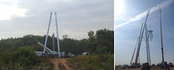
The ECI and Valmont engineering groups further collaborated to finalize structure designs and shop drawings for each tripod structure. The uniqueness of these structures required engineering oversight above that typically expended for traditional transmission structure types. After the structural components were fabricated, a trial fit of all structures was performed prior to delivery to ensure constructability, and to provide installation methods and procedures to the contractor.
ECI also provided on-site engineering and inspection services during construction. Overall, the innovative tripod structure configurations were successfully designed, fabricated and constructed, and are in operation today.
Jaron T. Reay is a structural engineering professional working in the power industry. He graduated from the University of Utah with a MSCE degree in 2004. He worked as a design engineer and project manager at Electrical Consultants Inc. for 11 years and is now the manager of transmission engineering in the company’s Salt Lake City, Utah, U.S., office. He is a member of ASCE and the Structural Engineering Institute’s technical activities division’s committee to create a manual of practice on guidelines for wood pole structures for electrical transmission lines.
Abe Dilworth is a professional engineer working in the power industry. He graduated from the University of Utah with a BSCE degree in 2006 and a MSCE degree in 2008. He has been working for Electrical Consultants Inc. for nine years as a project engineer and project manager. He spent seven years in the company’s Salt Lake City, Utah, U.S., office before transferring to its office in Phoenix, Arizona, U.S., where he is currently working as a project manager over transmission line projects.
