It is not often Dominion has to battle a structure fire caused by an improper switch operation, but it happened in the fall of 2010. The results of this event, and the potential for similar events to occur, prompted Dominion transmission engineers to reevaluate their transmission switch application and design. The questionable guyed H-frame switch structure was a design used extensively on the Dominion system and, therefore, raised a great concern for public safety as well as operational reliability of the transmission grid.

With support from multiple tiers of the management team and a sense of urgency, the transmission engineering group quickly formed a task force of structural, electrical and line engineers. The team's goal was to create a switch structure design and application that met the criteria of being compact, cost-effective and, most of all, safe to operate. In just four months, the team met the goal with in-house design and fabrication of the new Dominion self-supporting switch structure.
The Existing Switch Structure
The structure under evaluation was the guyed H-frame switch structure that supported both the transmission line conductor and the loads from the vertically mounted switches. The structure itself was an H-frame configuration made up of two light-duty poles that were weathering steel, slip-joint connected, longitudinally guyed and directly embedded into the earth (with no concrete foundation).
The conductor was double dead-end on a standard tubular-steel crossarm. The frame to support the switches was galvanized structural steel tubing, 8 inches (203 mm) in height and width, and 30 ft (9.1 m) long with a side-wall thickness of 0.188 inch (4.76 mm). The problems this structure encountered were unequal installations of longitudinal guyed tensions, differential ground settlement and overall lack of structure rigidity under wind loading.

The major issue was when the structure experienced loading from forces applied to the conductor. The structural steel tubing of the switch frame support was deflecting as much as 2 ft (0.6 m) when a wind event occurred that produced conductor loads. Movement of the switch frame support was resulting in the switches working their way out of adjustment, setting up the perfect trap for a partial opening or not opening at all. With so much movement on both the structure and the switch frame support, the switches were no longer within their operational tolerance for deflection.
This structure was embedded directly into the earth, which often led to differential ground settlement. This type of ground settlement occurs when one pole settles deeper than the other. This scenario was found to move the switch frame support out of alignment, forcing the switches out of adjustment even further.
Another problem encountered was the unequal longitudinally guy wire tensions. Unequal tensions essentially meant, of the four guy wires, two were tight and the other two had become loose. This often occurred because of improper guy anchor installation or the poles were settling into the ground. Again, this led to an overall imbalance on the structure and only helped to further knock the switch frame support out of a plumb alignment, cascading the effects to the switch adjustments and their operational tolerance.
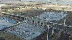
Self-Supporting Switch
The concept of the new self-supporting switch structure was to isolate the transmission line from the switches. Zero impacts from any conductor loading event on the structure meant the new structure would only support the switches.

Installation of the new self-supporting switch structure requires a floating dead-end to be cut into the transmission line and risers dropped down to the switches now supported on the new structure. The new structure also includes a designed concrete foundation and anchor bolts instead of the direct-embedded method used on the previous structure.
Concrete foundations vary in depths in accordance with the soil properties, which are subject to change throughout Dominion's territory. However, conductor loads are out of the picture now as the loads necessary to design the foundations became more predictable, making the design depth for the foundations practically standardized. Two types were designed for this structure, a drilled pier and a spread foundation. Drivers for the choice of which foundation to use are based on the equipment that will be used under the transmission line and the soil conditions at the structure location.
Added Benefits
Other design benefits of this structure include a reduction in outage durations, the ability to install the structure while the line above is energized, enhanced shipping logistics, a less than 0.5-inch (13-mm) deflection under wind loading conditions and streamlined parts with simple bolted connections.
Taking an outage on a transmission line in today's environment is not always an option. The self-supporting switch structure helps with this issue. With proper clearance to the energized line above, the self-supporting switch structure allows the construction of the foundation and even the erection of the structure under energized conditions. Traditional methods using the older-style guyed H-frame meant installing another structure within the transmission line itself, which often came at the price of a lengthy outage. The self-supporting version simply goes underneath.
Construction Options
In areas where proper clearance is not available and the line above requires an outage to install the structure, the outage times still have been reduced significantly. The reduction in outage times is a direct result of the efficiencies built into the structure itself as well as the process as a whole.
The foundations can be installed under the line. Then, two structures, all applicable hardware and two sets of switches arrive on a single flat-bed truck (later termed a “full tap on a flat bed”). Sealed 5-gal. (19-l) buckets are used to store all necessary hardware to erect each structure; in effect, this keeps all parts and pieces in a neat package for expedited material handling and reduced human error. Fewer parts mean fewer mistakes. Precise 3-D exploded views of the erection diagram mean clarity in the eyes of construction crews, and a structure that is finally symmetrical means there is no wrong way to install it.

Dominion is investigating the benefits of having the switches mounted to the switch frame at the manufacturer's level and having the manufacturer make the adjustments prior to shipping. These modular installations essentially have the frame of the self-supporting switch structure preassembled from the switch manufacturer with the switches already attached when delivered to the job site. The only thing left to do is to attach the frame to the poles and connect the leads to the main line above. This has proven to be an effective installation method in areas where the topography of the land is flat and the overhead clearance to the energized transmission line is adequate for safe construction and placement of the module.
Successful Design
Dominion's team of engineers and management staff were faced with a problem and, in turn, created a solution that improved the design, delivery and operability of switches on Dominion's transmission system. As of the third quarter of 2012, Dominion has installed more than 26 115-kV and six 230-kV self-supporting switch structures. The improvements to Dominion's switch replacement program have been a phenomenal success with the introduction of this new structure. Reduced outage times and worker hours, increased reliability, and improvements that focused on both engineering principles and process-specific goals helped to make this structure a success for Dominion.

Jared R. Williams ([email protected]) is a transmission engineer with Dominion Virginia Power. He has a BSCE degree from Old Dominion University and a MBA degree from Virginia Commonwealth University. Williams also has experience in land development as a consultant prior to joining Dominion.
Company mentioned:
Dominion | www.dom.com