In 2009, the Alberta Electric System Operator (AESO) directed AltaLink L.P. and EPCOR Distribution & Transmission Inc. to prepare a facility application for a system reinforcement transmission project near Fort Saskatchewan, Alberta, Canada. Known as Alberta’s Industrial Heartland, Fort Saskatchewan is home to many petrochemical production and oil-refining facilities.
The Heartland Transmission Project (HTP) was required to connect a new 500/240-kV substation, built in the Gibbons-Redwater region of Fort Saskatchewan, to an existing 500-kV transmission system on the south side of the city of Edmonton. A new double-circuit 500-kV transmission line, approximately 65 km (40 miles) in length, was required to make the connection. AltaLink Management Ltd. in a joint venture with EPCOR formed the HTP, with SNC-Lavalin T&D as the engineering, procurement and construction management firm.
Fortunately, some 30 years earlier, the Alberta government recognized the need to designate space for future roads, utilities and pipelines around Edmonton and established a transportation and utility corridor. At the time, the corridor was the far reaches of the city, but growth and development over the past three decades had pushed a mix of residential, commercial and industrial users up to the city’s borders. The HTP set out to develop line routes and connection locations to meet the electrical demand.
Project Development
While the prospect of developing a double-circuit 500-kV transmission line is exhilarating for engineers, the project development faced public scrutiny and objection. Businesses, homeowners, school boards, environmental lobbyists and stakeholders of all sorts voiced their concerns and contested the project development. Extensive feedback was collected through public consultations and open houses held in the project vicinity.
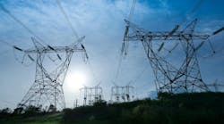
Using the information collected, the project team included four options in the facilities application to the Alberta Utilities Commission. Two options included traditional double-circuit lattice towers following two different routes, one east of Edmonton and the other to the west. A third option used a more slender tubular-steel monopole design along the east route. The fourth option considered an underground cable solution along a portion of the east route.
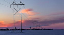
On Nov. 1, 2011, the Alberta Utilities Commission approved the HTP and granted a permit to construct and a license to operate the line following the east route using lattice-steel towers for most of the line. A condition of the decision required the use of tubular-steel monopole structures for approximately 10 km (6.2 miles) of the line between the cities of Edmonton and Sherwood Park. With an in-service date in the third quarter of 2013, the project team had less than 24 months to design, test, deliver and construct the tubular monopole structures needed for this section of the line.

Project Requirements
To meet the 3000-MVA load requirement, a triple-bundle 1590 aluminum conductor steel-reinforced (ACSR) Falcon conductor was selected. Overhead shield wire and optical ground wire were used both for lightning protection and as a communications link between the substations. To minimize the width of the right-of-way, a double-circuit vertical configuration was selected.
The terrain of the line route was considered relatively straightforward. Although there were many interactions with existing and planned infrastructure facilities, the topography was generally flat, and the team only had two major river crossings with which to contend.
A more challenging aspect was designing for the local climate. Extreme cold temperatures with heavy, wet snow and wind events are common in winter. Conversely, summer can bring frequent thunderstorms with strong sustained winds as well as extreme gust events such as plow winds, also known as downbursts, and tornadoes.
While the Canadian Standards Association (CSA) dictated the minimum requirements, the AESO set the performance criteria. Through extensive weather data collection and line performance analysis, the AESO dictated environmental loading requirements to address many of the local operating conditions.
Structural Capacity
The HTP used both the CSA’s heavy loading parameters (12.5 mm [0.5 inches] glaze ice with 400 Pa of wind) and AESO’s wet snow and wind parameters (50 mm [1.2 inches] wet snow with 245 Pa of wind) to evaluate the maximum vertical and transverse capacity. Along with the traditional maximum capacity cases, the team considered unbalanced broken wire and ice-shedding conditions to ensure tangent and angle structures had longitudinal capacity. The team also considered construction and maintenance tie-off loading of -30°C (-22°F) with 45 Pa of wind for initial conductor stringing.
Operating Requirements
While designing the line for extreme loading conditions ensured the line would remain intact during major weather events, more frequently occurring weather conditions were considered to ensure the line’s reliability. To limit the line trips from phase-to-ground faults, the HTP team evaluated tangent and suspension angle structures for clearances under weather conditions expected to occur frequently. Conductor-galloping and ice-shedding conditions were evaluated to limit the line disruptions from phase-to-phase contacts, as well.
Maintenance Requirements
Along with robust reliability criteria, the line also was required to be highly available. Outage availability for any 500-kV facility is often infrequent and short lived. As such, routine maintenance such as hardware, insulator and conductor accessory replacements would likely need to be completed while the line was energized.
To permit live-line maintenance, the team designed the structures with additional working clearances. Working clearance above the bottom and middle arms was included as well as clearance for a conductor cart beneath the insulators.

Detailed Design
With the project requirements accounted for, structure geometries began to take shape. The double-circuit 500-kV vertical configuration, with triple-bundle Falcon conductor, resulted in a tall structure that generated extremely high loads. To save costs through reduced structure weights and foundations sizes, the team designed a wider range of monopole structures.
Tangent structures were divided into light and heavy duty, and suspension angle structures were light and heavy up to 16 degrees. Because only three dead-end structures were required, they were designed specifically for the applied loads at their locations rather than meeting maximum span and line angles of a theoretical structure design.
The HTP team used PLS-CADD primarily for the line layout and PLS-POLE for preliminary structure design. Further detailed deflection analysis was completed using SAP2000, but arm connections and flange joint details were checked using traditional hand calculations.
Fabrication and Load Testing
Through the competitive bidding process, the contract to fabricate the tubular structures for the HTP was awarded to Zhejiang (Shengda) Steel Tower Co. Ltd. Fabrication was completed at the company’s factory in Hangzhou, China.
For tubular-steel structures, welding is one of the most critical details. To ensure a high-quality product, Acuren was sent to inspect the facility welding procedures and certificates prior to the contract being awarded. Representatives from SNC-Lavalin in Shanghai performed daily inspections during the bulk manufacturing process, ensuring all machine and manual welds were completed to the correct standards.
To ensure confidence in the design and fabrication, one completed structure was shipped to the China Electric Power Research Institute (CEPRI) in Beijing, a subsidiary of the State Grid Corp. of China, for full-scale load testing. Capacity limitations of the testing facility only permitted the testing of a tangent structure.
CEPRI mainly tests lattice towers, so a custom base adapter was built to attach the tubular-steel pole to the test bay floor. Loads were applied to the structure using cables attached to hydraulic rams. Dynamometers were placed in the tension cables and deflections were measured using a total station theodolite. Strain gauges also were placed at key areas of interest.
The most critical load cases were selected for testing. During one of the maximum loading tests, the structure deflection exceeded the maximum stroke of the hydraulic rams. With the loads held by temporary anchors, the hydraulic pistons were reset to a position that would allow the test to continue to the maximum loading. This situation was not anticipated, and while it caused some initial concern, it only resulted in a short delay in testing.
At completion of the testing, the behavior of the structure matched the predictions of the PLS-POLE and SAP2000 analysis models. There were no observed structural failures, and deflections were found to be within the allowable limits.


Foundation Design
In general, a single monolithic caisson is the preferred foundation for a steel monopole structure. Readily available piling equipment had a practical drilling diameter of 3 m to 4 m (10 ft to 13 ft). Geotechnical evaluations along the right-of-way indicated the presence of soft clay till and wet sandy soils. With small allowable lateral deflections at ground line, 3-m-diameter caissons would need to be 20 m (66 ft) or more in depth and require 150 cu m (5297 cu ft) of concrete.
The reinforcing steel cage would have required a 100-tonne (110-ton) crane to support it. Along with the piling machine, a pump truck to tremie the concrete and a hydrovac to remove excess water would have been required to be positioned around a 3-m-diameter opening. The coordination to complete this task safely — while getting the quality product required — was considered too risky from a cost and schedule perspective.
The alternative was to drill the foundations for the structures in the stronger, shallower soils with spread footings and pile clusters with caps. This construction method required smaller and more manageable steps, which carried lower risks and would produce a higher-quality product.
Right-of-Way Access
With the design and full-scale testing complete, and delivery contracts in place for the monopole structures, construction activities for the right-of-way preparation and foundation construction were well underway.
While the monopole section was only 10 km of the total 65-km line length, completing the construction within an already congested transportation and utility corridor was far more challenging than the remainder of the line that mainly crossed agricultural land. A concurrent-ring road project, which paralleled the monopole section, introduced new interchanges, overpasses, storm ponds and overhead facilities. Negotiating setbacks, slopes, finished-grade elevations, and temporary and permanent access required constant coordination between the two major projects, both striving to meet aggressive deadlines.

Foundation Installation
To resist the uplift and compression forces generated by a lattice tower, foundations made up of either screw piles, cast concrete piles or spread footings are used. With large tubular monopole structures come massive ground line reaction forces that need to be resisted. As the monopole foundations were limited by a 3-m maximum diameter, and with generally unfavorable soil conditions, straight-shaft caissons or driven-steel piles were not an economical option.
The pile-group and spread-footing foundations were challenging to build from a soil conditions perspective. Excavations required dewatering during the summer, and formworks had to be heated prior to placement during the winter. It was steel work required to tie the individual piles to the pile caps and pile caps to the anchor bolts that proved to be far more time consuming and tedious than anticipated.
Assembly and Erection
Structure assembly and erection of the tubular monopoles advanced quite efficiently compared to the lattice towers on the remainder of the line. Poles fitted with slip joints of bolted flanges fit together as expected, and structures were stacked and ready for conductor within a day or two. The more timely process was preparing the site access and staging the various pieces of equipment into position.
With structures up to 70 m (230 ft) high and weighing up to 135 tonnes (149 tons), and some individual sections weighing 20 tonnes (22 tons), the equipment required to erect these structures was large. For the heaviest structures, a 350-tonne (386-ton) crane was required to raise the structure sections. A 75-m (246-ft) telescopic crane fitted with a man basket was needed to position workers making the connections, and a second 150-tonne (165-ton) crane was needed for support as the individual sections were lifted into place.
Laying out all the assembled structure sections along with the equipment required a lot of space. With soft ground conditions around the structures, near football-field-sized areas of access mats had to be placed strategically to get equipment into the right places to complete the lifts safely and efficiently.

Project Completion
Monopole structures do have an advantage to lattice towers when it comes to erection and assembly times, but there is a trade-off in structure weight and foundation sizes. Details such as soil conditions and access, which may seem insignificant in the planning phase, can lead to major impacts on the construction cost and schedule later.
The development and implementation of monopole structures for this 500-kV transmission line was an incredible undertaking. Successful completion of the project was the result of extensive planning and preparation by many people. From the first designers who completed outline geometries, to the crane operators who lifted the structures into place, to the construction workers who torqued the bolts on the flange joints, everyone’s role was critical and contributed to the project’s success. ♦
Kishor Kumar is a senior civil engineer with the engineering standards and support group at AltaLink L.P., a Berkshire Hathaway Energy company. He is a registered professional engineer in the provinces of Alberta and Ontario, Canada. Kumar has more than 22 years of transmission lattice, steel and wood pole structures and line design experience. He is currently involved with the American Society of Civil Engineers Wood Pole and ASCE 10 Tower committees.
Jason Dwyer is the technical lead for the lines and civil engineering group at AltaLink L.P., a Berkshire Hathaway Energy company. He is a registered professional engineer in the province of Alberta, Canada. Dwyer began his career in the line maintenance group, where he learned the fundamentals of transmission line design and construction. In 2011, Dwyer was assigned the project engineer role for the 500-kV Heartland development, where he spent four years bringing the project from design to completion. Dwyer has since returned to the line maintenance group, where he now mentors junior engineers in the art of line design and project development.