In Japan, electric utilities have installed underground cables on transmission systems up to 500 kV to supply electric power to urban areas. Construction of these underground cables connecting power plants and urban or suburban areas took a long time to complete. However, older power plants have been replaced, making it necessary to increase the capacity of existing circuits or replace the aged cables.
The majority of underground cables in Japan are installed in ducts and tunnels. One advantage of this installation method is cable can be installed on an as-needed basis because additional civil engineering work does not have to be performed simultaneously. Conversely, if the required number of circuits needed exceeds the design number of available ducts or tunnels, new underground facilities have to be built, which is a challenging issue in urban areas because of the vast capital cost and construction time required.
Japanese utilities have taken advantage of recent developments in innovative technologies for increasing transmission capacity and replacing cable, which has contributed to the completion of many extra-high-voltage (EHV) cable projects in which existing ducts and tunnels could be used.
Triplex Cable
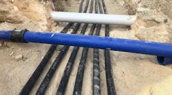
One of the largest cable construction projects ever undertaken in Japan is a cable capacity enhancement project using existing tunnel space. This project followed the replacement of a thermal power plant and the inevitable increase in generating capacity. A total of 20 circuits, involving the installation of 111 km (69 miles) of 154-kV cable and eight circuits with the installation of 13 km (8.1 miles) of 66-kV cables, were installed. Some 201 km (125 miles) of time-expired cables were removed during this capacity-enhancement project.
The largest challenge was to install four 154-kV cable circuits in an existing tunnel that already housed three 154-kV cable circuits. Typically, an additional 3 km (1.9 miles) of tunnel would have been required, but the use of triplex cable avoided normal measures to accommodate cable thermal expansion and contraction, often referred to as snaking.
Normally in Japan, a single-core cross-linked polyethylene (XLPE)-insulated cable would have been used for 154-kV cable circuits. Installing single-core cables in a tunnel requires design for cable snaking at a predetermined pitch and width as a countermeasure against cable thermal expansion and contraction. However, with the triplex cable, such expansion is absorbed by change in the triplex cable diameter. This twisted flexure saves expansion space and allows for more efficient use of the underground space from a 2-D perspective.
There are other efficiency advantages between single-core and triplex cables:
- Reduction in cable installation work and a significant reduction in accessories such as cleats, cable supports and other hardware
- Reduction in space required in the cable joint pits and inside the manhole sections
- Reduction in the space required for cable drums.
The change in design practice to using triplex cable avoided the construction of a new tunnel, reducing the project time period and overall expenditure.
The electrical performance of the XLPE-insulated triplex cable was considered adequate given its basic structure is identical to the XLPE-insulated single-core cable. Still, cable-bending mechanical and thermal behavior verification tests were conducted during triplex cable development, including an application evaluation.
Previously, the XLPE-insulated triplex cables were used for specifications up to 66 kV and 600-sq mm (0.93-sq inch) circular compact-stranded wire copper conductors. For this 154-kV project, the triplex cable had 1,000-sq mm (1.55-sq inch) segmental copper conductors. Verification was required to ensure the conductors were not affected by cable bending, and the thermal expansion and contraction were absorbed by means of diametric expansion.
The triplex cable occupies less space than conventional cable, which was a huge savings on civil engineering costs. This project was completed on schedule in December 2008.
Existing Cable Use
A plant replacement project led to the construction of new 275-kV cables to supply an inner-city area. However, to avoid replacing the cable circuits, the transmission system was reinforced with additional 275-kV cables. For this project, three circuits were installed that involved 18 km (11 miles) of 275-kV cable to allow for a 1,500-MW increase in generation capacity. A new 275-kV Y-branch joint was developed to enable connection between the new solid dielectric cable and the existing self-contained oil-filled (SCOF) single cables.
To achieve synergy in the usage of XLPE-insulated and SCOF cables, an insulation component made of epoxy was designed as the primary insulating body. On the XLPE side of the joint, a premolded insulator and prefabricated straight joint were used. This resulted in a composite structure that uses a compression ring (spring unit) to apply appropriate pressure at the boundary between the cable and the epoxy insulator. The oil-filled cable side used an insulated oil-impregnated paper and the epoxy bell mouth, resulting in a structure that allows for dimensional compatibility between the premolded insulator on the XLPE side and the inner dimensions of the epoxy insulator. The contact surfaces of the ferrule and embedded electrode are silver-coated. It was experimentally confirmed that no corrosion arises at the contact of the two metals, even if the silver coating is damaged. The electrical performance of the joint satisfied the Japanese Electrotechnical Committee Standards.
Although a forced water-cooling cable system was installed, the installation of a new cooling station appeared necessary to satisfy the increased load-transfer capacity of the circuits. However, the proposal to install a new cooling station was deemed practically impossible due to cost and finding a suitable location.
As an alternative measure, a cooling booster pump was developed to enable the hydraulic circuit length of the chilled water to be extended and to increase the cooling capacity. It has been confirmed elevation differences within the water-transfer route do not lead to any booster pump operational problems. Furthermore, verification tests on the water-transfer system did not reveal any significant design problems.
Construction of the XLPE cable installation was completed in June 2007. The cooling-water upgrade was finished in June 2009.
Cable Replacement
A 275-kV SCOF cable with joints positioned on an incline was subject to repeated movement between the core insulation and outer aluminum sheath. As a permanent solution, the existing cable was replaced with a 275-kV XLPE-insulated cable.
When replacing cables, the new cables are generally installed in the space vacated by the removal of the existing cable. However, this was not possible without a lengthy circuit outage, so this solution could not be adopted. Therefore, the replacement 275-kV cable was installed on a different route in an existing cable tunnel.
The new 275-kV XLPE-insulated cable was designed with a laminated aluminum water-shield layer, and it was necessary to install a Y-branch joint for this XLPE-insulated cable. Installation required a long cable pull in the tunnel. The resolution to both of these construction issues reduced the project cost and circuit outage time.
Future Optimism
Transmission system operators in Japan acknowledge the workload associated with the uprating and upgrading of existing cable systems, necessitated by increased system demand and future plant replacements, will increase. Although new construction technologies are available, they are becoming more difficult to implement due to the lack of underground space. Furthermore, there is a general problem of securing equipment and construction space in densely populated urban areas.
Japanese utilities have developed and implemented many new technologies — such as triplex cables, Y-branch joints and laminated aluminum water-shield layers — to increase the effective use of existing system assets. These new technologies will help meet the challenges posed by current social demands for electric energy, and there is considerable optimism regarding their future and diverse applications.
Acknowledgement
The authors express their gratitude to S. Katakai of J-Power Systems Corp., T. Nakajima of VISCAS Corp. and M. Owashi of Exsym Corp. for their help and support in preparing this article.
Shinichi Tsuchiya ([email protected]) received BSEE and MSEE degrees from Tohoku University, Japan. He has been engaged in all technical matters concerning the design, construction and maintenance of underground transmission with the Underground Transmission Group of Tokyo Electric Power Co.
Tomohiro Kiguchi ([email protected]) received BSEE and MSEE degrees from Yamanashi University, Japan. He has been engaged in all technical matters concerning design, construction and maintenance of underground transmission lines in the Underground Transmission Group of Tokyo Electric Power Co.
Makoto Nishiuchi ([email protected]) received BSEE and MSEE degrees from Osaka University, Japan. He has been engaged in the design, development, construction and maintenance of underground transmission lines and submarine cables. Currently, Nishiuchi is the director of the district office responsible for the maintenance of power equipment at Kansai Electric Power Co.