Underground power transmission is an integral part of major metropolitan areas, and Washington, D.C. — where the confluence of political, social and, yes, electrical energy come together to direct and support the lives of people throughout the United States and the world — is no exception. With a history that started in the late 1800s, the Potomac Electric Power Co. (PEPCO), a PHI Service Co., and predecessor companies have been serving the district and areas of Maryland dating back to the Washington Traction and Electric Co., a street car company.
Over such an extended time, the power system has evolved with the ever-increasing demands to supply the energy needs of the district, and PEPCO is continuously challenged with meeting those needs. As part of the effort to enhance reliability and meet energy demands of the area, PEPCO — recognizing a migration in power generation outside of its region — constructed a 230-kV pipe-type cable system to connect major power substations in the district and neighboring Maryland along a 5.4-mile (8.7-km) route and incorporated 21st century smart technology into aspects of the line to optimize performance and control of the system.

The cable for this project was manufactured by The Okonite Cable Co. and consisted of a 3,000-kcmil segmental copper conductor with 0.5 inches (12.7 mm) of laminated paper polypropylene (LPP) insulation and two D-shaped stainless-steel skid wires. PEPCO contracted with W.A. Chester to install the 8.625-inch (220-mm) Schedule 40 (0.25-inch [6.4-mm]) cable pipe and to pull, splice and terminate all of the cable.

Taking the Cable’s Temperature
Old-school methods for measuring temperature typically involved a copper-constantine Type-T thermocouple junction with test leads run to a hand-hole for spot measurements with handheld meters or recording using battery-operated data loggers. These point sensors only measure the temperature at one location, and cable conditions can vary over short distances along the length of a circuit. As a result, hot spots — combinations of installation conditions and soil characteristics that limit ratings — may be missed, allowing the cable to operate above rated temperature.
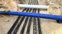
Fortunately, there is now a state-of-the-art alternative method for temperature monitoring. An optical fiber is installed in close proximity to the cable system to measure the temperature. Ideally, the conductor temperature itself would be measured, as this is the temperature that limits most ratings, but it is impractical because of the energized line-to-ground voltage and, in a pipe-type cable, is further complicated by the pressurized dielectric liquid within the steel pipe. So, 2-inch (50-mm) conduits were installed immediately outside of the cable pipes at the 10 o’clock and 2 o’clock positions to contain the temperature measurement fibers.
PEPCO routinely also includes conduits in the center of the trench in which to put communications fibers. On the new circuit, these are used in a dual role to measure the temperature, as well.
As a test bed for fiber-optic-based temperature measurements, PEPCO wanted the ability to compare measurements right outside the cable pipe with temperatures from the positions of the communications conduits to gain experience for possible retrofit applications on pipe circuits that only had the communications conduits. The new lines have four active fibers, although only two were needed for temperature monitoring and to provide feedback for real-time ratings. Spare fibers also were included in each fiber-optic cable in the event a fiber became damaged during the installation or operation.
Use of an optical fiber for temperature monitoring of cable systems was considered in the mid-1990s based on a physics principal first identified in the 1920s — another instance of marrying old and new technologies. Incident laser light pulses sent into optical fibers produce backscatter. This phenomenon, known as the Raman effect, uses the temperature-dependent backscatter and signal processing to determine the temperature approximately once every meter (3.3 ft) along the fiber, giving a complete temperature profile and thousands of measured values over PEPCO’s 5.4-mile-long cable pipes. This distributed measurement avoids missing hot spots.
LIOS Technology supplied the distributed temperature sensing (DTS) system used by PEPCO. Many DTS-based temperature systems use optical time-domain reflectometry common to the communications industry, but LIOS’ system is based on an optical frequency domain method for faster measurement times and generally improved long-term reliability. Usually communications fiber is a low-loss single-mode type, but, for improved temperature measurement accuracy (1C° [1.8F°]) and spatial resolution (approximately 1 m), a 50-micron multimode optical fiber was selected.

As part of configuring the system, PEPCO’s cable system design consultant, Electrical Consulting Engineers, P.C. applied knowledge of the installation conditions along the cable route and details from as-built drawings to identify zones of interest for the purposes of measuring temperatures that would be most important for ratings. The benefit to identifying zones is that a few tens of temperature values must be transferred to the utility’s supervisory control and data acquisition (SCADA) system rather than the thousands of values from the detailed DTS measurements. If detailed studies are needed or PEPCO requires more information, the complete temperature measurement traces are still available on the system located in the substation.
Temperature traces and the corresponding zone temperatures are measured every 15 minutes, as this interval was deemed to be a reasonable balance for the processing time for each temperature measurement with the relatively long thermal time constant of the buried cable system.
In addition to the cable temperatures, loops of optical fiber were installed at three burial depths — 3 ft, 6 ft and 9 ft (about 1 m, 2 m and 3 m) — remote from the power cables and any other heat-producing sources to provide an ambient temperature input for rating calculations. The 3-ft to 9-ft range was representative of the range of depths for most of the installed cable along the route.

The Real Deal on Real-Time Thermal Ratings
Traditional cable system design requires developing the ampere capacity, or ampacity, rating of the cables. Methods for rating calculations are based on the 1957 Neher-McGrath paper and subsequent standards such as IEC 60287. These methods require knowledge of the cable system construction from a manufacturer’s cut sheets, expected circuit loading patterns (daily load and loss factors), as well as information about the installation conditions including trench geometry, circuit separation, type of special backfill used around the cable pipes and native soil characteristics.
Often, conservative assumptions are made because the cable engineer has incomplete and imperfect information about the characteristics. Some parameters such as ambient temperature change on a seasonal basis, while circuit loading may change rapidly over the course of a few hours, affecting both load shape and preload conditions for emergency ratings. For typical static book ratings supplied to operators, worst-case assumptions are applied to combat these unknowns, often at the cost of sacrificing some usable capacity on the cable system.
Real-time thermal rating (RTTR) systems monitor key cable system parameters, including circuit loading and measured ambient temperature, to avoid the overly conservative rating calculations and optimize the allowable power-transfer capability of the cable asset. PEPCO employed this technology with a LIOS-supplied system using a real-time rating engine from Cyme International.
In conjunction with defining the cable temperature measurement zones, unique installation conditions for all these locations were configured in the real-time rating engine model. The calculations incorporated the measured earth ambient temperature, measured load and real-time feedback from the measured DTS fiber temperatures near the cable pipes. Emergency ratings consider the circuit preload, and the real-time engine calculates new emergency values based on preload conditions, often providing a significant increase particularly for short-duration emergencies.
PEPCO selected normal ratings and several emergency durations that were programmed into the RTTR system. Calculated ratings were transferred from the RTTR computer to PEPCO’s SCADA system, where they could be used by system operators and engineers to evaluate the performance of the cable circuits and make market decisions on power transfer availability through the 230-kV pipe-type circuit.
As part of the configuration process, ratings calculated with the RTTR system were compared to book ratings to verify the system had been modeled correctly. The system was allowed to run to evaluate reliability and stability of the calculation results under varied conditions.

Poise Under Pressure
Dielectric fluid pressurization is maintained by a shipping-container-sized pumping plant to accommodate dielectric liquid expansion and contraction. MAC Products manufactured the pressurization plants. Old-school pumping plants used electromechanical control systems to regulate when pressurization pumps or relief valves activated as dielectric liquid in the pipes expanded and contracted with load cycling. While these types of systems are reliable, any type of alarm generally required personnel to go to the pumping plant locations to determine whether immediate intervention was required.
PEPCO’s Benning-Ritchie pressurization plants were designed with specialized solid-state programmable logic controller (PLC)-based monitoring systems that permit remote monitoring. When a trouble call comes in at any time, day or night, responsible personnel can check the entire state of the pressurization system remotely using a portable computer or by logging on to PEPCO’s energy management system.

Smart Pipe Cable Challenges
Implementation of the smart technology did not come without some hitches. One of the biggest challenges was addressing the utility’s network security protocols. The DTS and RTTR systems were supplied by vendors outside the United States and had similar but not identical communications protocols to that of the utility.
Furthermore, the temperature monitoring and real-time rating packages were based on computer systems that were non-native to systems that had been vetted by the utility’s network security personnel. This meant the systems had be introduced to the hardened data connections to receive real-time load and measured temperatures from the utility network — acting as a master device — and to post calculation results to the SCADA system — acting as a slave device to PEPCO’s network. Making the neurons talk to one another required addressing challenges on many levels. As smart as the system turned out to be, closing the synapses took some time.
Ultimately, the Einstein treatment proved effective for the pipe-type circuit and is expected to allow PEPCO enhanced power-transfer capabilities over other circuits in addition to better monitoring and control throughout the expected 40-year life of the cable system.
Christopher W. Schnetzler ([email protected]) is an engineer in underground transmission engineering with the Potomac Electric Power Co., focusing on underground transmission systems. He holds a BSCE degree from the University of Maryland and a Fundamentals in Engineering certificate.
Mousa Hejazi ([email protected]) worked with Greehorne & O’Mara Inc. (Stantec) for 15 years before joining PEPCO Holdings Inc. He is responsible for management of civil engineering and consulting services for the planning, design and construction management of infrastructure projects involving utility systems and roadway improvements. Hejazi holds a BSCE (environmental option) degree from George Washington University and a master’s degree in engineering management. He is a registered professional engineer in Maryland.
William A. Lopez ([email protected]) is the lead engineer and technical advisor in PEPCO’s transmission group and the project manager for special projects. He holds a BSCE degree from the University of Maryland and a master electrician license in Maryland and Virginia. Lopez worked for EMS Inc. as an environmental electrical control specialist for three years before joining PEPCO in 2000 as distribution engineer.
Earle C. “Rusty” Bascom III ([email protected]) worked with underground cable systems for Power Technologies Inc. and Power Delivery Consultants Inc. before founding Electrical Consulting Engineers, P.C. in 2010, where he is president and a principal engineer. Bascom holds an associate’s degree in engineering science, a BSEE degree and master’s degree in electric power engineering from Rensselaer Polytechnic Institute, and an MBA degree from the State University of New York at Albany. He is a senior member of the IEEE Power & Energy Society, a voting member of the Insulated Conductors Committee and Standards Association, a member of CIGRÉ, and a registered professional engineer in New York, Florida and Texas.
Companies mentioned:
Cyme International | www.cyme.com
Electrical Consulting Engineers, P.C. | www.ec-engineers.com
LIOS Technology | www.lios-tech.com
MAC Products | www.macproducts.net
PEPCO | www.pepco.com
The Okonite Cable Co. | www.okonite.com
W.A. Chester | www.wachester.com
Sidebar: What Is Pipe-Type Cable Anyway?
The original oilostatic technology is derived from a blend of 1880s kraft (German for strong) paper-production methods with concepts developed for electrically insulating pressboard, initially used in power transformers in the 1920s. Pipe-type cables were first patented in the 1930s, recognizing the benefits in insulation properties by pressurizing the dielectric liquid in combination with the paper tapes.

PEPCO first applied these systems on its system in 1957 with 69-kV circuits. In the pipe-type cable system, grade-A carbon-steel-pipe sections are welded together in a cable trench using backing rings before being backfilled with thermal sand or fluidized thermal backfill. The steel pipe is an integral part of the system, so a corrosion coating and cathodic protection system are used to protect the pipe. Pipes connect substations to intermediate manholes, where splices are located and contained within welded casings.
Cables are constructed of stranded copper or aluminum conductors with helically applied kraft paper or laminated paper polypropylene (LPP) tapes saturated with dielectric liquid. Shield tapes and skid wires are applied over each cable for mechanical protection, and the three cable phases are simultaneously pulled through the installed cable pipe. The pipe is evacuated of moisture and pressurized to a nominal 200 psi with dielectric liquid; pressure is maintained from pumping plants at one or both ends.
Though there is a definitive trend toward other cable types (for example, extruded cables), underground transmission systems in North America have predominantly used pipe-type cables into the 1990s, with utilities relying on the proven paper-insulation technology and long, successful operating history with these systems by many utilities. Pipe systems continue to be used on a select basis where space constraints limit available trench and manhole dimensions for extruded systems, and where directional-drilled crossings may be required and benefit from long allowable pulling distances of pipe cable.
Aside from the nuance of LPP tapes — a sandwich of kraft paper and polypropylene tapes — in the 1970s, pipe-type cable systems have largely been left unchanged for decades. However, this does not mean there are not new approaches to the way these systems may be designed, installed and operated.