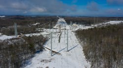
Transmission congestion on Hydro One Inc.’s double-circuit 115-kV line — St. Catharines and Hamilton, Ontario, Canada — made it problematic for the utility to supply reliable power to its customers in the fast-growing Niagara peninsula. New industries, cities and highways have been built over the past 80 years of the line’s life. Because of this rapid increase in electricity demand, the two circuits — Q5G and Q2AH — have reached critical values of ampacity and sag.
To meet the growing electricity demands, Hydro One had two options: build a new transmission line or upgrade existing circuits. With increasing public refusal to have a new transmission line built in their communities, the less publicly opposed strategy was to modify existing towers and conductors to accommodate the increasing power demands.
Hydro One’s project to modify existing towers and conductors would double the continuous power flow and increase the emergency flow from 136 MVA to 295 MVA. It also would increase the fault current capacity from 6000 A to 13,000 A. And line clearances and structures would be upgraded to the current design standard, meeting the present loading criteria for Hydro One structures.
Numerous Challenges
The requirements to upgrade these circuits presented numerous challenges. The scope required the structures — which were built in 1922 and suffered from corrosion — to be repaired and reinforced to the current loading standards. It also required fixing the existing substandard clearances to the latest clearance standards. In addition, the easement agreement did not allow any new structures or changes to the centerline of the existing right-of-way. Furthermore, the environmental approvals limited the number of allowable towers that could be raised to 25 structures.
To add to these challenges, 15 km (9.3 miles) of distribution line that ran adjacent to the existing circuits had to remain energized throughout construction. The team had to bear in mind that the circuits crossed under two 230-kV lines and over several distribution lines as well as 52 roads and railway crossings, all of which were built after the original circuits were constructed.

The Upgrade
All 44.6 km (27.7 miles) of these circuits were originally constructed in 1922 on a double-circuit 115-kV 1920s-type family of towers. The existing conductor was aluminum conductor steel-reinforced (ACSR) 54/7, 605 kcmil with maximum operating temperatures of 85°C (185°F) for the Q5G circuit and 110°C (230°F) for the Q2AH circuit. The towers also supported a 5/16-inch (7.9-mm) galvanized-steel shield wire. In addition, the QG5 circuit was running at 25 Hz while the Q2AH circuit was at 60 Hz.
To increase emergency power flow from 136 MVA per circuit to 295 MVA per circuit, the existing 605 kcmil ACSR was replaced with 21/7 ACSR 997.2 kcmil (Ontario/TW) conductor. In addition, the thermal rating was increased from 85°C to 150°C (302°F) at the ambient temperature of 35°C (95°F). Furthermore, the fault current capacity was increased from 6200 A to 13,000 A, by replacing the existing 5/16-inch steel shield wire with 7 #8 Alumoweld.
All clearances were upgraded to the latest Hydro One clearance standards. The structures also were upgraded to the latest Hydro One security class C loading standard. This included 25 mm (1 inch) of radial ice alone, 12.7 mm (0.5 inch) of radial ice plus 80-kmph (50-mph) gust wind and 129-kmph (80-mph) gust wind alone.
Damage Assessment
Hydro One’s line engineers and field technicians inspected the line. They identified numerous clearance, structural and foundation issues that were addressed to refurbish and upgrade the line.
The existing line also suffered from chronic clearance issues. Several industries were using the land under the circuits and adjacent to the towers, encroaching on the existing conductor clearances. In addition to the unauthorized use of the right-of-way by these other industries, several distribution circuits also were constructed adjacent and crossed under the existing circuits, and 230-kV transmission lines crossed over the circuits in two locations.
Several of these locations had existing substandard clearances that would need to be addressed. In one location, distribution potheads needed to be moved to an adjacent pole and the distribution circuits buried. Line inspections found several structure modifications that attempted to address the various clearance issues. These included previously installed vertical tower extensions inserted above the footing, dead-ending bottom phases or moving bottom phases to middle arms, and installation of midspan structures.
From the inspection and damage assessment of the structures, many towers were identified as suffering from significant corrosion. Extensive damage assessment was done to determine the actual strength of the affected structural members. The deteriorated condition was taken into consideration during the structural modeling of the towers. Some of the towers also had members suffering from significant deformations or fractures.

Structural Analysis
During the tower inspection, certain rusted members of the towers were ground down manually until the rust was removed. The remaining steel thickness was measured in several locations and compared against the original tower member sizes. The percentage loss of steel thickness was related to the color of the rust and interpolated across the entire tower.
The rusted tower models with reduced member thicknesses were analyzed using the PLS-TOWER program, considering the new shield wire and conductor sizes. The extensive structural analyses and modifications were done to ensure the upgraded line met the latest Hydro One loading criteria, the latest electrical clearances and the galloping performance standard.
Final Design Stage
The final design of the circuits put all dead-end and suspension towers back into their original design configuration and removed all midspan (wood-pole) structures.
Analyses of the tower models showed several structural modifications were required to accommodate the increased tower loading. These modifications included new bracing members added to the structure to reduce the buckling lengths. Rusted members were replaced with higher-strength members as needed. Also, members were increased in size, thickness or both, and connection details were checked for ease of fit. The uplift capacity of some towers was increased with the installation of corrugated-steel cribbing at the base legs or soil mound.
To increase the conductor ground clearances, all towers had the bottom arms removed, and a new modified middle arm was designed to support both the bottom and middle phases. To ensure adequate electrical clearances between the top phase and the new extended middle arm, a concord hanger configuration was used. This provided 200 mm (8 inches) of additional clearance between the top phase and the new middle arm hanger.
Even with the additional clearance from moving the bottom phase to the middle arm, several spans still had ground clearance violations. The conductors either needed to be pulled tighter or the towers needed to be raised up. Increasing the tension was not feasible because of the already high conductor tension, thus tower rising was considered.
The standard method to raise towers was to add either a base-vertical shaft extension (if the existing footings would be reused) or a normal base shaft extension (if new footings would be installed). These were both expensive options, as large cranes are required to lift a fully dressed tower and a significant amount of steel would be required to be assembled by construction crews.
A new innovative lightweight shaft extension was proposed for this project. This shaft extension included installing a new tower panel at 1.524 m, 3.048 m, 4.572 m or 6.09 m (5 ft, 10 ft, 15 ft or 20 ft) between the existing bottom arm and middle arms. It required two smaller cranes, as construction crews were lifting only the top portion of the tower with one crane and the shaft extension with a second crane.
In addition, less steel was required because of the smaller size of the tower shaft above the bend line and less time for construction to install. Overall, the shaft extension resulted in major time and cost savings.

Shaft Extension Installation
Construction crews carefully planned the stages of this project. There was an outage on both circuits during this work. The top phase on the first circuit was moved from the top arm to the shaft of the tower. The middle phase was removed from the middle arm, and the arm was removed and lowered to the ground. Repeating on the other circuit, the top and middle phases were removed, and the first crane lowered the middle arm to the ground. Then the second crane was attached to the peak of the tower. Supporting the peak, the construction crew unbolted the tower legs.
The peak of the tower was lifted into the air and supported with the crane. The first crane used to lower the middle arms then raised the new shaft extension up to the existing tower. The construction crews bolted the shaft extension onto the tower, just above the original bottom arm. After the shaft extension was bolted onto the old tower, the original peak was lowered onto the shaft extension and bolted back to the tower. The middle arms then were added to the tower to carry the bottom and middle phase. Finally, the bottom phases were relocated onto the new middle arms and the bottom arms removed.
Galloping Performance
After the circuits were raised, the galloping performance of the circuits was analyzed. It was determined interphase spacers were required because of the line configuration and the substantial winds and ice found in this area.
The wind spans in this line vary between 113 m (370 ft) and 281 m (923 ft). In general, spans greater than 213 m (700 ft) were likely to gallop in double loops; however, because of the importance of this line, ellipsis overlap was not allowed. It was assumed all spans galloped in single loops, and the Davison method (Ontario Hydro method) was used. The loading condition associated with galloping was 12.7 mm (0.5 inch) of radial ice concurrent with 130 Pa of wind pressure.
PLS-CADD software was used to check the galloping, and interphase spacers were used to eliminate the ellipsis overlaps. The galloping analysis revealed an overlap between the ellipse of the top phase and the ellipse of the bottom phase (relocated on the modified extended arm). In theory, the extended arm could be modified to create an offset between the top and bottom phases. However, this would have made the modified arm larger and more expensive, as well as reduced the shielding of the outermost middle phase.
A Cost-Effective Method
Although Hydro One has more than 100 years of experience in building new transmission lines, as well as in damage assessment and refurbishment of existing structures, this was the first time a lightweight shaft extension inserted above the tower’s waist line was used to double the power-transfer capacity of a 90-year-old transmission line built in heavily populated urban and industrial areas. This cost-effective method for upgrading towers using lightweight, flexible shaft extensions was a radical departure from the conventional tower extension method, where a tower extension is inserted above the footings level. This innovative approach led to a significant reduction in project cost and construction time, and also minimized construction disruption in urban areas by enabling the use of smaller cranes for tower modifications. ♦
Karen Callery received a BSCE and MSCE degrees from Queen’s University. She is currently a senior design engineer specialist in the transmission engineering department at Hydro One Inc. With extensive experience in the design and refurbishment of transmission lines, Callery has published more than 10 technical papers on the impact of extreme weather on transmission lines, damage assessment, refurbishment and the upgrade of transmission structures. She is the recipient of the 2013 Hydro One’s President Award.
Ibrahim Hathout received a Ph.D. degree in civil engineering from the University of Waterloo. He is currently the senior manager of transmission engineering at Hydro One Inc. Hathout has extensive experience in design, maintenance and rehabilitation of transmission structures. His research interests include reliability assessment as well as applications of fuzzy logic and neural networks to damage assessment of existing structures. He serves on several CSA and IEEE committees and was the 2012 recipient of Hydro One’s President Award for Innovation.