Fault-Blocking Converters for DC Networks
The most commonly used type of VSC for HVDC today is the “half-bridge” version of the Modular Multi-level Converter (HB-MMC). In this circuit, the converter is made up of large numbers of identical submodules, each comprising a large capacitor and two semiconductor switches (IGBTs ). As the HB-MMC cannot suppress currents that occur for faults applied on the DC side of the converter, the usual method for clearing such faults today is to rely on the AC circuit breakers that connect the converter to the AC grid. However, this is – in power electronics terms – very slow, taking 60-100 ms. DC circuit breakers would be much faster. Alstom has established a strong technical position in such DC breaker technology, and solutions based on this should be commercially available in the near future.
“An alternative could be to modify the converter itself so that a DC breaker is not needed,” said Davidson. “This is what the ‘full-bridge’ version of the MMC (FB-MMC) does.”
The FB-MMC, which Alstom was the first manufacturer to propose (in 2009), uses four semiconductor switches instead of two in each submodule. Considered today as a viable short-term option when a VSC is needed for multi-terminal DC networks, the FB-MMC submodule is ready to be used not only in HVDC but also in an updated version of Alstom’s STATCOM offering. However, the FB-MMC is not the optimum type of fault-blocking VSC because its cost and power losses are considerably higher than that of an HB-MMC.
To address this shortcoming, Alstom is developing an improved fault-blocking converter, called the Alternate Arm Converter (AAC).” (See sidebar.)
Fault-blocking converters such as the FB-MMC or the AAC would be good solutions for relatively small DC networks with only three or four terminals – as well as for point-to-point schemes using overhead lines, where faults due to lightning strikes can be frequent. Clearance of DC faults in such schemes would require all of the converters feeding into the DC network to be blocked briefly.
The converters can then be de-blocked again shortly after to see if the fault is still present. If it is not, the network can then be re-started. However, if the fault is permanent (as is usually the case with cable faults) then the entire DC network would remain blacked out until maintenance technicians can fix the cable – which may require weeks. However, if a DC network extends over a large geographical area or has a large number of terminals, it becomes a critical element in the whole power transmission system and as such cannot be out of service for an extended time. So, there would be a need for additional means to rapidly isolate the faulted section so that the remaining, healthy part(s) of the DC network can resume operation.
“For this we do not need a DC breaker, since the converter has already interrupted the fault current. We just need a ‘fast disconnector’ that can open rapidly to isolate the faulted section,” points out Davidson.
Controlling the opening of these fast disconnectors requires some clever algorithms.
“A common feature for all fault and HVDC equipment types is that, in a steady state, the sum of cable terminal currents should equate to zero, as there are no loads connected along the cable and any current that enters the cable at one end must leave the cable through the other end,” explains Andrzej Adamczyk, Team Coordinator of DC networks. “If a fault occurs, an additional current path appears within the faulty branch and the cable current sum is therefore going to be non-zero – in fact, always positive.” On the other hand, in a healthy branch, as there are still only two terminals through which the current can enter or exit the cable, the cable current sum will remain zero.
“However, as the length of transmission lines is typically in the range of tens to hundreds of kilometres, the cable propagation delay may reach several milliseconds and transiently the current sum will be negative in a healthy cable section,” he adds. It is therefore possible to identify whether the fault lies within a given cable section by looking at the sign of the transient cable current sum: “If the sum has a negative value, the fault is not in that branch; if it is positive, then the fault is located within this section.”
Such a detection algorithm has already been validated by testing its operation on a four-terminal meshed HVDC grid, one of the most challenging network topologies from a protection point of view because of the multiple conduction paths for the fault currents.
The Alternate Arm Converter (AAC)
Three questions to Kevin J. Dyke, Alstom’s Research and Technology Department Manager
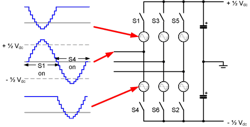
In an MMC, each of the six “valves” needs to contain enough submodules to be able to produce the entire DC voltage, but for much of the time this full voltage rating is not necessary. The AAC removes this requirement by having a separate “director switch” in series with the submodules. The director switch consists of a stack of IGBTs connected in series but it allows the number of submodules to be reduced by almost half. This means the power losses are significantly reduced compared with the FB-MMC and are close to those of the HB-MMC – but with the added benefit of being able to suppress DC fault currents.


