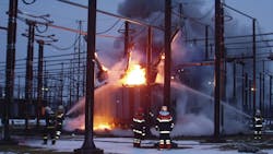
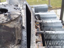
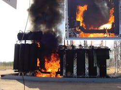
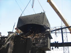
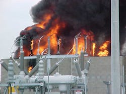
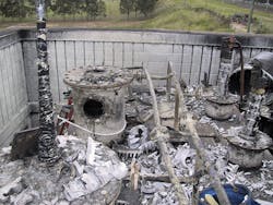
A large percentage of the power transformers in commission contain large quantities of mineral oil. While the probability of an explosive failure is low, it is not insignificant. In the event of an explosive failure occurring in a bushing, in a cable box or within the oil-filled transformer, there is a high probability it will develop into a serious or even disastrous oil fire, causing loss of the transformer and possibly other assets, loss of supply and, in the worst-case scenario, loss of life. Therefore, the potential for an oil spill and oil fire is a serious risk all owners and operators of power transformers must consider.
Risk and probability are expressions sometimes used indiscriminately to describe the probability of a transformer fire. However, as risk equals probability times consequences, it is important to differentiate between risk and probability when considering options for mitigating the risk of transformer fires. To reduce the risk of a transformer fire, either the probability or the consequences should be reduced, but preferably it is better to reduce both.
Reducing the probability of a fire occurring is mainly directed toward measures taken in the transformer design, whereas mitigation of the consequences is mainly directed toward the measures taken in the design of the substation and fire-protection system.
Failure Rates
The failure rate varies considerably between transformer users. It depends on the quality of the design and manufacture, the procurement policy, and the operation and maintenance practices. The type of transformer also is a factor, as failure rates tend to be above average for auto-transformers and generator step-up transformers, and below average for the two winding transformers installed on transmission and subtransmission systems in the 11-kV to 300-kV voltage range. Statistics confirm the failure rates increase on transformers with operating voltages above 300 kV, and the consequences of a failure fire is more severe on systems with high fault levels.
Data on the probability of a transformer fire is limited, but much more information is published on the probabilities of transformer failures. The probability of a transformer failure varies considerably among utilities and types of transformers, but the probability of serious failures is typically in the range of 0.5% to 2.5% per transformer service year, with an average rate of serious failures of 0.9% to 1.0% per year of service.
The average probability of a serious transformer fire is on the order of 0.06% to 0.1% per service year, or one fire per 1,000 to 1,500 transformer service years. In practice, this means 2.4% to 4% of all transformers can be expected to cause a fire during a 40-year service life. While the probability of a transformer fire is relatively low, it is not a negligible risk and certainly too high to adopt a do-nothing approach for most transformer installations.
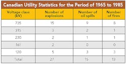
Statistics suggest geographical location, temperature and lightning levels may be attributed to transformer fires. For example, the first generation of 735-kV transformers installed in Canada had a high failure and fire rate, and South Africa (Eskom) and Malaysia experienced similar problems.
Typical Transformer Fire Scenarios
Transformer fires are predominantly mineral oil fires, and it is often assumed tank rupture is the dominant cause. However, this is an erroneous assumption, especially for voltage levels below 300 kV where failure of oil-impregnated paper (OIP) bushings and air- or oil-insulated cable boxes account for 70% to 80% of transformer fires, and on-load tap changers account for 10% to 15% of transformer fires.
The remaining 15% of transformer fires is attributable to a range of other causes. Transformer tank ruptures are rare for voltages less than 245 kV, as the arcing fault energy for these classes of transformers is often below the critical level of energy required to cause tank rupture.
Oil-Impregnated Bushing Fires
OIP bushings are the single highest cause of transformer fires. Many OIP bushing are based on a design where the lower and upper porcelains are clamped against O-ring seals at metal interfaces, and the clamping force is provided by prestressing of the central tube. The insulation in bushings is highly stressed, and there are inherent fire risks in the pre-stressed central tube design.
If any arcing failure occurs within an OIP bushing, it frequently results in an explosive failure, causing arcing in the air, an oil spill and a major oil fire. This is not the case with resin-impregnated polymer insulator bushings.
Cable Termination Failures
Cable terminations failures in air- or oil-filled cable boxes also result in a high percentage of transformer fires. The typical scenario with oil-filled cable boxes is the initiation of an arcing fault in or at the cable termination. The pressure buildup from the arc ruptures the cable box explosively, ignites oil in or from the cable box, which continues and escalates as it gets fueled by oil spilling from the conservator or the main tank.
The common fault scenario for cable termination failures in 11-kV to 33-kV air-insulated cable boxes is different, but the outcome is frequently a major oil fire. An arcing fault in an air-insulated cable box without arc venting will, in most cases, result in complete destruction of the cable box.
Mechanical forces on the cables from the explosive pressure forces and the fault current will often cause breakage of the bushings, and the oil spilling from the broken bushings will then be ignited by the arc.
Tank Ruptures
Tank ruptures mainly occur at very high voltages (more than 300 kV), but it is interesting to note failures within windings rarely cause tank ruptures. The majority of tank ruptures are caused by the breakdown of the insulation between the high-voltage connections and the tank, or the bushing turret, or from the lower part of the bushing to the tank or the bushing turret.
The reason for this is the arcing energy for an inter-turn, inter-disc or inter-winding fault is, in most cases, much lower than the arcing fault from a high-voltage connection to the tank or high-voltage connection to the bushing turret. The arcing current for winding faults is usually less because of the winding impedance as the pressure rise is partially constrained by the windings. However, tank ruptures are of serious concern as they can cause the release of a large quantity of oil and rapid escalation of a fire.
Internal Arcing and Tank Ruptures
The calculation of arcing energy is, in principle, very simple to evaluate as the arc energy is a function of arc current times voltage times the duration of the arc. The arcing current and duration are often known, but the voltage across the arc is not. In the absence of that knowledge, it can be estimated to be 10 V/mm to 15 V/mm (255 V/inch to 380/inch).
Conversion of the arcing energy to pressure on the tank structure to determine the withstand capability and rupture point of the tank as well as the effectiveness of venting is a complex study, which ideally should be, but rarely is, undertaken by the manufacturer at the design stage.
Mitigation of Transformer Fire Risk
If a fire occurs as the result of a transformer failure, then the transformer is nearly always a total write-off. Therefore, utility owners and operators need to adopt a strategy that includes the following:
- Minimizes the probability of a fire occurring.
- Protects the remainder of a substation installation from a potential transformer fire.
- Maintains supply during a fire or, if that is not possible, restores the supply as early as possible after the fire.
- Avoids pollution and contamination of the environment.
The fire triangle provides very good graphic representation of what is required to initiate and maintain a fire and, therefore, also how a fire can be prevented or extinguished. If any one of the three elements — fuel, heat or oxygen — is removed or absent, then there will not be any fire.
Mitigating the risk of a transformer fire is a multi-stage approach. The first stage is directed toward minimizing the probability of a transformer failure developing into a fire. Duplicate system protection and fast clearing circuit breakers minimize the arcing time and reduce the risk of tank rupture.
The next stage is to minimize the probability of transformer failure by the specification and selection of components of good quality with low fire risk. The following recommendations provide maximum risk reduction per unit of expenditure:
- Use high-voltage resin-impregnated paper polymer bushings in preference to OIP bushings.
- Avoid the use of cable boxes or, if unavoidable, use pressure and arc venting on cable boxes as is common on metal clad switchgear, or alternatively consider a plug-in cable connection.
The opportunity is now available to consider the use of less flammable fluids. Ester-based fluids are increasingly used in transformers with voltages below 132 kV and, in a few cases, at higher voltages. However, the percentage of medium and large transformers using these fluids is still very low with only a few transformers below 132 kV insulated with these fluids in service. Dry-type and gas-insulated transformers (GITs) are virtually explosion proof with nearly no fire risk. However, SF6 is a potent and costly greenhouse gas, so its application is mainly constricted and rarely used in Europe and the United States.
Improved tank designs and various forms of pressure venting can reduce the risk of tank rupture for arcing faults close to the venting port, where the vented product is mainly arcing gases. However, it must be stressed that, for arcing faults more than 1 m (3.3 ft) away from a venting port where the vented product is mainly oil, the pressure vents or rupture discs cannot prevent tank rupture if a high-energy arcing fault occurs inside the tank.
Japan is the only country with a national guide on the design of transformer tanks to withstand arcing for a time sufficient for the system protection to operate and clear the fault. The combination of reinforced tank design and pressure venting has proven effective in reducing the risk of a tank rupture and, consequently, a transformer fire.
Protection of Substation Assets
The positioning and installation of all substation assets needs to be considered at the substation design stage. Processes methodologies such as hazards and operational (HAZOP) and failure mode and effects analysis (FMEA) have been developed for this purpose.
Often, it is useful to categorize substations into types of designs where specific standard strategies can be applied for fire risk management:
- In open-air substations, where land cost is low, space separation will often be the most economic fire victim risk management strategy.
- In compact air-insulated substations, where land cost is higher, fire barriers in the form of reinforced concrete panels and walls, sound and fire enclosures, or water spray curtain are common forms of fire protection.
- Underground or substations located in city buildings will normally have a site-specific, fire-prevention and fire-contingency management strategy. The installation of GITs, low-flammable fluid and oxygen, excluding fire protection or a special tank design, are measures commonly adopted for inner-city substations. For smaller power transformers, dry-type transformers or transformers using high-flame-point fluids (low fire risk) are possible options for the reduction of transformer fire risk. Dry-type and SF6 transformers are the safest option as they have virtually no fire risks.
- Deluge or fogging water spray systems can be effective in the protection of fire victim assets and are often used on unit and generator step-up transformers at power stations where high capacity and reliable water supply is readily available.
Standard Precautions
Several standard precautions apply to all substations that should be considered at the design stage:
- Access to key areas of the substation with any one transformer on fire; multiple access points may be necessary.
- Radiated or wind-borne heat should not be able to initiate fires in other substation assets.
- Fire brigade access and availability of water, foam or other fire suppressants for firefighting. Water is effective in reducing heat output and preventing the fire from spreading to adjacent assets, but it is generally not effective in extinguishing transformer oil fires; foam is not effective in fighting oil fires with oil spilling over vertical surfaces.
- Oil spillage outside the substation during a fire should be prevented. Failure to contain spilled oil should not be considered an accident, and failure to foresee and manage such a risk is negligence. Regulating authorities in many countries now apply heavy fines if an oil spill occurs outside the substation boundaries. Therefore, oil containment systems are becoming a standard feature in most substation installations. The containment systems should be sized to ensure all oil from the largest transformer in the substation can be contained. In Australia, underground oil and water separation tanks are widely used that separate transformer oil mixed with water to less than 10 ppm of oil in the water. One Canadian utility uses a mat/membrane system suitable for cold climates, which allows water to flow through but retains the oil.
- Oil spilled from a fire source should not be able to travel along cable trenches or conduits, so the use of cable segregation and fire barriers is recommended.
- Evaluation of the cost of losses incurred as a result of major transformer fires confirms the value of contingency planning. In a study by a large property insurer of 100 random loss events, the average-loss cost of these incidences exceeded US$7 million compared to $4 million when proper contingency plans were in place.
Contingency Planning
This review of transformer fires indicates the need for utilities to develop contingency plans to minimize the impact of the total cost of losses. There is evidence from industry insurers that contingency planning can significantly reduce the impact and cost of losses attributable to transformer fires.
Arne Petersen ([email protected]) received his bachelor’s degree in engineering from RMIT Melbourne and a MBA degree from University of Queensland (Australia). Following five years of experience as a transformer design engineer, he spent the next 27 years as a transformer specialist and manager of a high-voltage plant for Powerlink Queensland. Petersen currently is an independent consultant specializing in transformers and has conducted transformer failure investigations in Australia and southeast Asia. He is a chartered engineer and a fellow member of the Institution of Engineers Australia. He is an active in CIGRÉ as a technical advisor to the CIGRÉ Study Committee A2 – Transformers and the convener of CIGRÉ Working Group A2.33 – Transformer Fire Safety Practices, which recently published the CIGRÉ Technical Brochure 537, “Guide for Transformer Fire Safety Practices.”
