In February 2011, Memphis Light, Gas and Water (MLGW) embarked on a challenging electric substation construction project. Electric substation 3, built in the 1930s, needed to be expanded and modernized to address power-quality issues on the network created by overhead distribution faults connected to the same operating bus. There also were issues related to equipment fault current interruption ratings, obsolete transmission voltages and equipment end-of-life concerns.
The construction site required a federal brownfield project to be initiated to clean up the expansion site environmentally. Additionally, the property purchased to expand the substation held unmapped and unknown underground obstructions that required creative decision making to complete the site preparation. Finally, modern design improvements were made to address the unique design of the substation that feeds the southern part of the electric network in Memphis, Tennessee, U.S.
Federal Brownfield Project
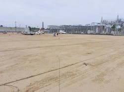
Phase one of the project was to environmentally remediate soil on the property adjacent to the substation to accommodate the substation expansion. The area was more than 3.4 acres (1.4 hectares) and up to 13 ft (4 m) deep. On the expansion site, 40% of the soil qualified as special waste soil, so a remediation plan had to be developed. To expedite construction and remediate the special waste-level contaminants, MLGW followed federal brownfield guidelines so the property could be used for the new electric substation.
The U.S. Environmental Protection Agency defines a brownfield as follows: “Real property, the expansion, redevelopment, or reuse of which may be complicated by the presence or potential presence of a hazardous substance, pollutant or contaminant. Cleaning up and reinvesting in these properties protects the environment, reduces blight and takes development pressures off green spaces and working lands.”
For the utility to use the site for the substation expansion, it was critical that it be made safe for the MLGW crews who would perform the construction. Ground grids, subsurface drainage, cable trench and top portions of manholes and electric duct line (which comprised the majority of the underground infrastructure) were all located in the top 6 ft (1.8 m) of the remediated soil. The manholes and duct lines that were deeper than 6 ft required excavating localized deeper areas and filling them with crushed gravel.
The special excavation gravel would be re-excavated at a later time to accommodate the deep duct line and manhole installations. Finally, a barrier layer of gravel was required so future crews disturbing the soil would be forewarned when they were working in or approaching unremediated soil.
Construction Obstructions
Perhaps the most challenging portion of the environmental soil remediation was encountering unmapped obstructions and unstable soil. The first obstruction encounter was an unmapped 8-inch (203-mm) sewer line, which was discovered running diagonally across the expansion site and routed directly under what was to be the new control house. Moreover, the 8-inch line terminated in a previously unmapped sewer manhole discovered under the existing substation.
As construction progressed, a second unmapped 6-inch (152-mm) sewer line was discovered; it ran adjacent to an existing mapped electric duct line routed across the new construction site. The 6-inch line was discovered when rainwater on the site kept draining from an unknown location. Environmental crews searched and found the 6-inch line with a hole in it — where the rainwater was going.
The biggest surprise of the remediation phase was discovering a 24-inch (610-mm) unmapped storm drain that split the site neatly into two sections. The storm drain terminated in the underground Memphis drainage system, known as the Little Bettie Bayou, located directly under the 12.47-kV bus work in the existing substation.
Lastly, four large sinkholes, measuring up to 1,000 cu ft (28 cu m), developed during the removal of the special waste soil. The sinkholes were caused by old trees, trash and cinder-type soil that collapsed and sank as it was disturbed. One sinkhole was located under the location for the new control house. It would have been catastrophic if the sinkhole had developed after the new station was completed. All of the underground obstructions were GPS mapped for future reference.
The newly discovered sewer lines and storm drain could not be cost-effectively or operationally relocated or terminated. As for the 24-inch storm drain, it turned out to be the main water-collection route for the immediate area. Smaller drains from the 24-inch drain fingered out six blocks north, east and south of the station. Given the size of the drain and scope of its drainage area, it was unbelievable the drain did not appear on any city or utility infrastructure map.
For their protection, the sewers and drains were bridged in high-pressure nonexcavatable flowable fill. The flowable fill is a cement compound that can flow into cracks and crevices to protect the sewers and drain from heavy equipment traffic and future dig-ins.
Substation Design
Nothing was particularly unique about the existing station design of substation 3. It was a main-and-transfer-type station served by two 25-MVA, 115/12.47-kV station transformers. Additionally, the station had 15 distribution circuits, each equipped with a reactor to minimize bus dips during feeder circuit faults and to limit available fault current to nearby network customers.
The uniqueness of the station is its history. The station was completed in 1939 and served part of the 125/216-V alternating-current (ac) network power grid in the southern downtown area. This grid was the first ac secondary power network in the world in about 1907. Additionally, the original subway-type transformers were the world’s first implementation of network protectors, which have reverse-power relaying to isolate the secondary grid from backfeeding primary voltage feeder faults.
The southern Memphis ac network is currently comprised of 10 underground 12.47-kV network circuits that feed 108 transformers. The transformer secondary sides are connected in parallel to form the southern network power grid. Primary feeder fault isolation allows the remaining network primary circuits to continue serving the secondary power grid through the remaining transformers on the unaffected circuits. The reliability of the network system is such that some MLGW customers have gone as long as 15 years without an outage.
The 1939 substation was originally designed with five 23-kV transmission sources, and the distribution bus voltage was 4 kV. In the mid-1950s, the station was converted to its current 115/12.47-kV operational configuration.
During the mid-1950s station retrofit, a 115-kV high-pressure fluid-filled (HPFF) underground transmission system became the primary transmission source and the five 23-kV circuits were relegated to contingency status. The 115-kV underground transmission system was the 11th HPFF system over 100 kV installed in the world. In the current construction project, the 23-kV lines were taken out of service to keep the fault current levels within the limitations of the equipment.
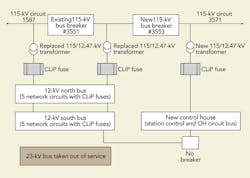
The 23-kV transmission sources were replaced with a third 12.47-kV station section. G&W Electric current-limiting protectors were added to the three station transformers and network feeders to limit fault current. Additionally, five overhead distribution circuits were transferred to the new section to isolate them from the 10 network circuits feeding the network system.
Current-Limiting Protectors
A significant station improvement was the addition of the G&W current-limiting protectors, or CLiP fuses, which replaced the distribution feeder reactors. They have logic circuits to detect fault current levels that will exceed the rating of the connected protective devices and — using small, self-contained pyrotechnic charges — quickly open a faulted circuit.
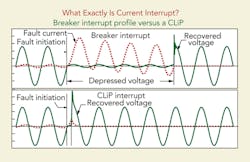
The protectors clear faults in a time frame of a fourth of one cycle and send a command to the protective breaker to open and isolate the unfaulted phases instantaneously. The fuses are being used on the secondary of each station transformer and on each of the 10 network 12.47-kV circuits.
The five overhead circuits do not need reactors or fuses as they are isolated from the network bus by a normally open sectionalizing breaker and a 115/12.47-kV station transformer. The primary benefits of using CLiP fusing are the virtual elimination of depressed voltage during substation bus or circuit faults that exceed a preset magnitude. The resulting effect is a reduction of available fault current, a significant reduction in overall fault energy, increased feeder capacity and a reduction of arc-flash energy exposure to workers.
Problems Solved and Advantages Gained
In addition to limiting fault current and mitigating depressed voltage events, the CLiP fuse technology solved several concerns plaguing substation 3.
In recent history, a hard distribution feeder fault (network or overhead) would result in depressed voltage for some MLGW customers. The landmark Peabody Hotel elevators were famous for stopping during these types of circuit events. Once during the substation 3 construction project, an overhead circuit experienced a hard fault. The resulting depressed voltage caused a power outage at the FedExForum arena 45 minutes before a Memphis Grizzlies basketball game. Power was restored in time for the game, but MLGW reps had to explain, in depth, how the station improvements in progress would mitigate this type of event in the future.
The CLiP fuse also considerably lowers energy delivered during a bus or feeder fault. The voltage-depressing event would be cleared by CLiP fusing approximately 20 times faster than traditional breaker and reactor protection with an energy level of approximately 1% of a typical substation breaker protection. This reduction in overall energy is less damaging to connected equipment. It also significantly reduces the likelihood for potential injury to any utility workers near the fault by reduction of arc flash energy, blast and propelled debris.
Past experience at other utilities with this type of protection has shown arc flash/blast has been reduced to nonevent status in terms of worker harm.
Choosing to use CLiP fusing also turned out to be a source of significant cost savings in several ways. On the original substation 3 distribution circuits, the current-limiting reactors previously in service were consuming US$55,000 per year in power losses. The reduction in losses is projected to be valued at approximately $3.2 million over the life of the station. It is also worth noting that, prior to the installation of CLiP fuses, the feeder reactors limited the rating factor on the network circuits at about 350 A. Because the rating of the feeder CLiP fuses is 1,200 A, they are not the limitation of the feeder circuit, and the cable/duct bank becomes the limiting factor of each circuit at about 425 A. This is a gain of about 20% in the available capacity of the station, or about two additional circuits.
The Project Concludes
Substation 3 construction is in the final stages. All of the new station transformers are in place, the new control house is in operation, and the transformer and feeder CLiP fusing is in place. When construction is completed, customers of the MLGW southern electric network should enjoy the high level of reliability and power quality they have come to expect from their hometown public utility.
Acknowledgments
The author would like to thank Philip Cox, a professional engineer with MLGW, for his valuable and constructive suggestions during the final editing stages of this article. He also thanks Tony Federico of Northwest Contracting Services Inc. and Matthew Garner of BH&M Environmental for providing environmental photos and remediation information.
James B. Warberg Jr. ([email protected]) is an electric matrix planner coordinator, responsible for overall electric construction resource analysis for the Memphis Light, Gas and Water Division. His responsibilities include analysis of resources, construction scheduling analysis, and application of engineering analysis in safety and PPE issues. He holds a BSEE degree with a minor in mathematics from The University of Memphis. He is a registered professional engineer in Tennessee.
Companies mentioned:
G&W Electric | www.gwelec.com
Memphis Light, Gas and Water | www.mlgw.com


