Microgrids have become one of the most commonly debated topics at industry con-ferences. In recent years, the advancement and development of different technologies and communications has led to the launch of multiple microgrid pilot projects in the United States. The majority of these microgrid projects share the same objectives:
- Gain a better understanding of current technologies and distributed energy resources
- Develop control algorithms to operate in grid-connected and islanded modes
- Understand how different technologies interact with each other within the microgrid
- Examine potential use cases for distributed generation in power system operations.
The U.S. Department of Energy defines microgrid as “a group of interconnected loads and distributed energy resources, within clearly defined electrical boundaries, that acts as a single controllable entity with respect to the grid [and can] connect and disconnect from the grid to enable it to operate in both grid-connected or islanded mode.”
Simply having photovoltaics (PV) installed on the roof of a house or having a backup generator does not constitute a microgrid. However, if these two are combined, or energy storage is added as an alternative to a generator, a microgrid is born. Currently, the main issues with microgrids that need to be resolved are the maturity of interconnection standards, the economic challenges and the low utilization efficiency of energy storage.
Putting these issues aside, in the last several years, Duke Energy deployed two microgrid pilot projects with the objective to understand and tackle the engineering issues and distributed intelligence platform associated with microgrids. Thus, within the last two years, Duke Energy’s Emerging Technologies Office (ETO) has designed, implemented and commissioned two operational microgrids in the Charlotte, North Carolina, area.
About the Microgrids
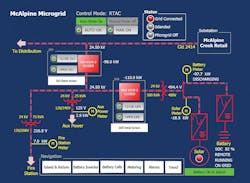
Duke Energy built its first microgrid in 2013 at the McAlpine Creek substation, located on the south side of Charlotte. Equipped with 50 kW of solar and a 200-kW/500-kWh battery energy storage system, the microgrid has served the City of Charlotte’s Fire Station 24 successfully since July 2015.
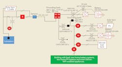
In 2015, Duke Energy built a second microgrid at its Mount Holly facility in nearby Gaston County. The microgrid consisted of a 650-kW/326-kWh and a 250-kW/125-kWh battery energy storage system, 120 kW of solar and roughly 500 kW of controllable load. Unlike the McAlpine microgrid, which used commercially off-the-shelf equipment in a conventional manner, the Mount Holly microgrid was the industry’s first reference implementation of the Smart Grid Interoperability Panel’s (SGIP) distributed intelligence technology framework and reference architecture known as the Open Field Message Bus (OpenFMB), which was successfully ratified as a standard by the North American Energy Standards Board (NAESB).
Using OpenFMB architecture, plug-and-play interoperability and local peer-to-peer communications were enabled between the assets within the Mount Holly microgrid. This architecture ultimately offered complete situational awareness, which provided Duke Energy’s ETO with a microgrid test bed for many lessons learned.
Lesson 1: Load Diversity
It is important to know the load diversity within the microgrid. To design the proper generation asset mix/portfolio and optimum capacity ratings, it is necessary to know the minimum, average and maximum load within the microgrid. Analyzing past years of load data and understanding the microgrid use case and objective (resiliency) should lead to a successful and optimal design.
Lesson 2: Engineering
Microgrid modeling, short-circuit study and direct-current (DC) arc-flash analysis are important engineering efforts. Distributed generation technologies within microgrid systems at McAlpine and Mount Holly are connected to a secondary 277/480-V Y-grounded system. In addition, loads within microgrids also are diverse (from 120 V to 480 V). The biggest challenge of doing three engineering analysis efforts is that the most commonly used software packages in electric utility distribution system planning do not have the capability to model the system secondary voltages.
DC arc-flash hazard study is probably the most important and critical part of designing the microgrid, and all arc-flash warning labels need to be created and installed at necessary locations. Canisters from the battery clean-agent fire-suppression system need to be placed at several locations within the microgrid, and a visit to the nearest fire station to introduce the battery system and discuss emergency response plans is a must.
Lesson 3: Protection
The inverter grounding system affects the system protection. The battery and solar inverters installed at the two microgrids have 315-V, 347-V, 380-V and 480-V alternating-current (AC) outputs, and typically the AC side is not grounded. Rather, these inverters can be connected only phase-to-phase, which reduces the choice of transformer configuration to either Yg-Y or Yg-Delta. Using Yg-Delta is not recommended, because during the fault conditions, the inverter would reduce the amount of fault current seen by the upstream protection devices, thus potentially increasing the chance of the relays not tripping on a fault.
For that reason, Yg-Y (floating) transformers were used for the connection to all inverters at the Mount Holly microgrid. However, this also required an additional grounding transformer (either zigzag or Yg-Delta) for the operation in islanded mode only. The only benefit of using Yg-Delta transformers is that the ground faults could be detected with undervoltage relay settings, thus reducing the need for installation of the grounding transformer. The drawback is that the technology connected to the DC side of the inverter could only be used in islanded mode.
Lesson 4: Battery
The battery is the Achilles’ heel of the microgrid. Every microgrid needs both a voltage and frequency source, and the battery can provide this service. However, the battery’s thermal management and its heating, ventilation, and air conditioning (HVAC) system design is very important. Given that each of Duke Energy’s pilot battery installations in the past five years had different thermal management challenges, the review and selection of the HVAC system requires a thorough understanding and special treatment.
Lesson 5: Aux Power
The battery auxiliary power requirement can be significant. “A battery is like a bucket of water with a hole on the bottom,” said Mike Rowand, Duke Energy’s ETO director.
The Mount Holly microgrid battery auxiliary loads were recorded to be in the 8-kW to 12-kW range, which translates to a daily energy consumption greater than its 125-kWh rating. For this reason, sizing the battery and PV properly is critical if islanded operation is required at all times. The easiest way to overcome the challenge of continuous islanded operation is to include a generator as one of the distributed generation technologies.
Lesson 6: Integration
Integration of dissimilar assets requires a lot of tedious work. One of the biggest challenges of building a microgrid is the system integration. Factory acceptance testing of individual assets can be successful, along with the site acceptance testing. However, system integration of different distributed energy resources is very challenging. One must not assume all the equipment comes configured as desired. Moreover, some new commercial products or systems could be missing meaningful documentation. Many new control schemes need to be developed, and most of them look great on paper.
Lesson 7: Coordination
Field commissioning coordination is never perfect. Creating a set of drawings for the field implementation becomes challenging because different assets within the microgrid have different time lines associated with the issuing of drawings as well as field delivery and installation. Wiring is done on several voltage levels: the 12.47-kV primary system, which requires one set of skills; followed by the 277/480-V and 120/208/240-V secondary system, which requires electricians; and then the 12 VDC, 24 VDC and 48 VDC for the communications equipment, which requires a third set of skills. Staying on time and target for a microgrid type of project is challenging.
Lesson 8: Backfeed
The interconnection agreement may not allow backfeed to the distribution feeder. In such a situation, it is necessary to create an optimization algorithm that provides net-zero power flow at the point of interconnection, so the system would be following the agreement and the power bill would be minimal. One such algorithm was implemented at Mount Holly, and it was based on keeping the real power as close to zero as possible at the point of common coupling (PCC), while keeping the battery state of charge within a desired optimal range.
Lesson 9: Backup Power
Each controller, communications device and relay device within the microgrid requires a properly sized uninterruptible power supply. Normally, any battery that needs to be available for seamless transition requires all systems to be up and running during the transition time. There are three ways to enable this capability. The first way is to add a generator and run it all the time, which is not economical. The second way is to connect the battery to the alternate AC source, which, in most cases, is not available. The third and preferred way is to use an internal uninterruptible power supply that could be either standalone or charged by the internal battery.
For that reason, every device used at the Mount Holly microgrid facility was designed with an uninterruptible power supply system that allows a minimum 5-minute operation without an AC source.
Lesson 10: Limitation
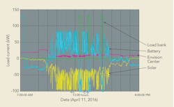
Continuous microgrid operation is limited. Testing at Mount Holly resulted in the microgrid running for a maximum of three days with a battery rated at 250 kW/125 kWh, PV rated at 120 kW (DC rating) and a maximum load of 50 kW (note the maximum load during the three-day period was in the 25-kW range). Using the same battery for the voltage and frequency source as well as the energy in absence of the output of the PV farm can result in a loss to the microgrid because of undervoltage.
Currently, a second battery is being added to the Mount Holly microgrid site. It will be strictly a power battery providing voltage and frequency. The existing battery will be used in current source mode, providing strictly kilowatt-hours. Using this architecture, it will be possible to extend the time when the system is operating in microgrid mode. Adding the second energy storage system increases the capital cost initially, but it also increases the reliability.
Relying on only one battery and PV might be challenging because of the number of likely overcast days in a row and the desired reliability of the microgrid. If the PV and battery are the only choices for the generation mix, they both would have to be oversized, which would rely on identifying additional benefits to the existing distribution system to which it is connected.
Standout Lessons
Of all the lessons Duke Energy has learned about microgrids over the last few years, three are standouts:
- “With microgrids, no matter how good the infrastructure is, it is nothing without reliable maintenance,” said Jim Rogers, former CEO of Duke Energy.
- If this is the first microgrid being designed, ensure the location of the microgrid is close to the distribution operating center, because keeping it operational will be challenging at first.
- Designing a microgrid can cost X dollars. Construction, testing and commissioning can cost 10 times X dollars. Maintaining and operating a microgrid with the same reliability as the feeder to which the microgrid is connected to — now that is priceless.

