In 2007, Portland General Electric (PGE) began planning to replace an 80-year-old substation and nearly 1.5 miles (2.4 km) of aging 15-kV submarine distribution cables to ensure both downtown Portland, Oregon, U.S., and the city’s South Waterfront District have an adequate supply of reliable power to support the area’s growth and development. Today, 11 years later, the $83 million Marquam project is nearing completion.
New 115-kV XLPE cables will carry power from PGE’s Harrison substation, east of the Willamette River, and over the new Tilikum Crossing Bridge to the new Marquam substation, close to downtown on the river’s west side. However, to bring power from the bridge to the substation, project engineers at Black & Veatch first had to run the XLPE cables 1050 ft (320 m) under 12 lanes of the busy Interstate 5 freeway, while dodging underground obstacles and negotiating varying soil types.
The Marquam substation also presented PGE and Black & Veatch with its own set of unique challenges. The designated location is a small urban lot, sandwiched between I-405 and I-5 and surrounded by numerous parkways, local roads and residential buildings.
“The Marquam project is PGE’s biggest investment ever in the downtown Portland power grid,” said Ezra Richards, PGE’s project manager. “It really amounts to a case study, not only in complex engineering but also a balancing act of managing dozens of contractors while working in a small and urban area.”
From the outset, PGE confronted several critical issues:
• What cable system would best meet the project goals?
• How would the cables come across the Willamette River?
• How would the team overcome construction challenges on a small and complex site?
• How would the substation tie to the distribution system?

Selecting the Cable
With Black & Veatch’s feasibility studies in hand, PGE selected 115-kV XLPE-insulated cable with a 2500-kcmil segmental copper core and a high-density polyethylene (HDPE) jacket to run from the Harrison substation west to the Marquam station. XLPE cable has become the worldwide standard for underground transmission because it is much easier to maintain than older technologies that rely on pressurized nitrogen gas or mineral oil for insulation.
The cable system is designed to carry a minimum of 1260 A continuously over a 40-year design life. The new line would have one cable per phase, each with a stand-alone distributed temperature sensing (DTS) system to monitor temperature, a continuous copper ground continuity conductor for fault return current, and a dedicated fiber-optic communications system. As such, the design would require six polyvinyl chloride (PVC) or HDPE conduits — one for each cable, and one each for the continuity conductor and for the fiber-optic line. In turn, each conduit would be encased in concrete or compacted sand to provide a thermally acceptable environment for the cables. The next two challenges were considerably more involved.
Bridging Portland’s Waters
An overhead span across the Willamette River was rejected because of permit and visual constraints, and horizontal directional drilling (HDD) beneath the riverbed was determined to be too costly. Thus, PGE determined the most suitable means for crossing the Willamette River was to run the cables through PVC conduits encased in the concrete deck of the future Tilikum Crossing Bridge, where they would be both protected from the weather and out of sight.
Because of shipping and installation limitations, PGE decided to splice the cables that cross the Willamette River to those running from the Harrison substation and to the Marquam substation in precast concrete vaults — one on each side of the Tilikum Crossing Bridge.
To construct the segment of 115-kV transmission line that runs from the vault on the west side of the bridge to the I-5 freeway, project engineers worked closely with local officials to run the lines under Porter Street, a busy new thoroughfare that provides access to the Tilikum Crossing Bridge for trains, buses, cyclists and pedestrians. The Porter Street engineers had to raise the elevation of Porter Street 12 ft (3.7 m) and support it on both sides with mechanically stabilized earth (MSE) retaining walls, which, in turn, are strengthened with metal or synthetic straps running horizontally from the face of the wall into the soil. Conduits for the 115-kV lines were then installed in a single layer between the MSE straps and encased in sand. Constructability was improved by designing the vaults to be set at grade prior to Porter Street improvements, then backfilled around the completed vaults as part of elevating the street.

Building the Substation
Everyone knew that building the Marquam substation would be a major challenge. Because of its location in downtown Portland, the site had experienced a few prior uses that left not only multiple underground obstructions but also a retaining wall that had existing knee bracing for stability on its south side. All of this is very closely located to where the 115-kV transmission lines would enter the substation.
In addition, at 290 ft long by 210 ft wide (88 m by 64 m), the site was small, considering its intended use and the construction space necessary to turn it into a state-of-the-art facility. Despite these challenges, PGE was fortunate to obtain the site in the middle of Portland’s dense urban environment. Because the ultimate build-out would include six 50-MVA transformers, and PGE wanted a breaker-and-a-half scheme for greater system reliability and operational flexibility, the utility selected a gas-insulated substation (GIS) design. This equipment allows energized phases to be located only inches apart, compared to air-insulated substations that typically require 10-ft (3-m) phase spacing.
Additionally, a 115-kV GIS often uses overhead bushing terminations to connect the incoming lines to the substation equipment; however, Marquam’s GIS required underground terminations to minimize space and maintain adequate electrical safety clearances. The limited site space made the application of an underground termination GIS an ideal choice, but the site required additional equipment:
• A 39-unit networked switchgear enclosure and provisions for a future 27-unit radial switchgear enclosure for the 13-kV feeder circuits
• A 60-ft (18-m) relaying control enclosure for the line and transformer protective-relaying devices
• Three 13-kV metal-enclosed shunt capacitor banks with future provisions for three more
• Four vaults on the north side to handle four outgoing bored casings for distribution lines
• A large vault — 100 ft long by 30 ft wide by 15 ft deep (30 m by 9.1 m by 4.6 m) — on the south side to collect incoming and outgoing XLPE transmission cables and to provide a foundation for the GIS equipment.
One of the biggest challenges resulted from having to build the incoming cable vault 10 ft from an old and suspect 25-ft (7.6 m)-tall retaining wall. That wall, which was supporting an existing street and nearby homes, was supported by dozens of knee braces that could not be removed. However, the knee braces were taking up valuable real estate needed for substation equipment. Under normal circumstances — for a wall of this height — tie backs would have been used to anchor the wall into the soil behind it, but with the property line just 3 ft (0.9 m) away, that approach was not an option. PGE determined the only solution was to build a second, stronger retaining wall 3 ft from the existing wall, and due to space limitations, a cantilever, soldier pile wall was the only option.
Black & Veatch engineers selected HP 18 x 204 steel bearing piles for the job, the largest such piles currently manufactured. Each 50-ft (15.2 m)-long steel pile was secured in a 4-ft (1.2-m)-diameter concrete-filled casing that extended 25 ft below ground level, leaving 25 ft of piling above the substation grade to support the new wall. The piles were spaced just 7 ft (2.1 m) apart along the full length of the wall.
Further increasing the degree of difficulty, the existing wall had to be supported continuously during the construction of the new retaining wall. This required an extensive construction coordination plan that involved installing piers between existing braces, connecting the existing wall to the new piles, then relocating braces one by one so the old wall was continuously supported. In addition, because of concerns about the integrity of the existing wall during construction, engineers installed tilt monitors along its full length. The monitors were sensitive enough to detect changes in the wall caused by temperature variations throughout the day and would provide an automatic warning to the project team if any movement beyond stringent tolerances were detected.

While the old wall proved stable during construction, the new wall did transfer an extreme load to the soil below. This necessitated significant bracing for the shoring of the large GIS vault excavation and the formwork since the excavation was only 10 ft away from the wall. The braced formwork remained inside the vault until after the roof slab was poured. The bracing was later removed through an access hatch. And while this major effort was underway on the south side of the lot, a jack and bore effort was taking place just 100 ft away on the north side of the substation.

Linking to the Portland Grid
Installing the 40 distribution lines PGE planned for the downtown Portland grid required four jack and bores, each was 4 ft in diameter and 235 ft (72 m) long, extending out from the north side of the Marquam lot. While typical bores are generally level, or may slope up at 1 degree, the 40-ft (12.2-m) elevation difference between the substation and the land on the other side of I-405 forced drillers to slope two of these bores from the Marquam substation upwards at 10.5 degrees and two others at 8.5 degrees. At one point, the bores ran 35 ft (10.7 m) under the freeway, between the foundations for the I-405 freeway, and tolerances were very tight.
The jack and bore contractor, Gonzales Boring & Tunneling, had to bore within 2 ft (0.6 m) of a concrete monolithic sewer line while staying a minimum distance from the foundations supporting I-405. At one point, Gonzales had to replace the normal bit on the auger with a rock bit to remove concrete debris, but generally the boring activities went flawlessly. The driller had to hit a 12-sq-inch (77-sq-cm) target, and he did.

However, getting to that point required meeting a lot of engineering challenges. The team first had to dig down to create a base for the boring machine — 40 ft by 50 ft by 26 ft deep (12.1 m by 15.2 m by 7.9 m) — on the Marquam lot. This required substantial shoring, but the receiving side on Caruthers Street was even more of a challenge because of its proximity to a 3-ft-diameter pressurized water line, the I-405 freeway, and a new school building. To monitor the impact to the school during installation of the shoring, PGE installed vibration monitors at the school, which was undamaged. To be a good neighbor and minimize disruption to school activities, major work on Caruthers was done outside school hours and during school holidays, and PGE maintained close communication with the school throughout the work.
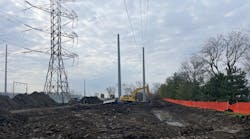
 next to the relaying control enclosure (right), located in front of the retaining wall. In the foreground (right to left) are three 50-MVA transformers, a 39-unit networked switchgear and three 13-kV metal-enclosed shunt capacitor banks. On the far left, next to the relaying control enclosure, four vaults collect the distribution circuits and route through the underground bores into downtown Portland.")
The Key to Managing Complexity
Flexibility and creativity were the keys to project success, as this was a lesson in designing around both ambiguity and complexity. The project had many engineering components — electrical, civil, overhead transmission, underground transmission and distribution — with complex site conditions and technical challenges. Thus, everyone had to work together very closely to develop a consensus at every point. Constant communication not only was required between PGE, Black & Veatch, the vendors and the supporting contractors, but it was also vital to PGE’s ability to continually match electrical with underground design and to ensure that all equipment was designed and built according to plan. ♦
Scott Stocker is a principal engineer at Portland General Electric and was the project engineer for the Marquam transmission project. Stocker has more than nine years of experience in transmission and distribution design. He is a registered professional engineer with a BSME degree from Oregon State University.
Ian Grant is a senior project engineer at Black & Veatch and was responsible for civil design on the underground project. Grant has more than 14 years of experience in underground transmission and substation civil projects. He is a registered professional engineer with a BSCE degree from the University of Portland.
Brenton Waechter Smith is a project engineer at Black & Veatch and was responsible for the electrical substation design. Waechter Smith has more than seven years of experience in substation design. He is a registered professional engineer in California and Oregon, with a BSEE degree from the University of Wisconsin-Madison and an MSEE degree from the University of Washington.