Condition Monitoring of Aging Transformers
Hydro-Québec has more than 2,000 grid and GSU transformers with an average age of more than 30 years in operation connected to its transmission system, which has a total installed capacity in excess of 200 GVA. The utility is in the midst of a major project to renew this transformer fleet, but it is well aware that the average age of these assets cannot be maintained at the current level due to several constraints, including financial and resource availability limitations.
In response to these challenges, the utility has adopted two strategies to maintain the required transformer availability in the coming years. The first strategy is to gradually renew the transformer fleet, starting with assets whose condition is cause for concern and most critical to the power system. The second strategy is to reduce failure consequence through remote monitoring and optimized maintenance.
Asset Management of Transformers
The main indicator for determining the internal condition of transformers is dissolved-gas analysis. Hydro-Québec takes an oil sampling of all its transformers on an annual basis and an oil analyses every four years. These procedures were adopted in the 1970s, and the database now contains more than 40,000 results. In parallel with on-site testing, Hydro-Québec implemented the continuous monitoring of transformers in the late 1980s with on-line gas monitoring, using Hydran technology on all of its new and existing 735-kV transformers and reactors as well as new 315-kV transformers. By the mid-1990s, Hydro-Québec extended the program to include all transformers rated 47 MVA/120 kV and above.
Moreover, in the late 1990s, the utility started to gradually replace its on-site temperature mechanical indicators with digital oil and winding temperature control and indicators, completing the suite of on-line monitoring devices installed on this transformer population. These developments have proved to be effective in detecting incipient faults in the main tank of transformers, improving cooling system control and improving temperature indication alarm and trip.
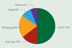
However, Hydro-Québec’s transformer reliability statistics show on-load tap changers (OLTCs) and bushings are the cause of two-thirds of all transformer failures. Consequently, Hydro-Québec’s Research Institute (IREQ) has been working to develop new technologies to monitor these two key components to make the transition from systematic maintenance to conditional and predictive maintenance using remote-monitoring best practices. The technologies are now in the industrialization process and will be commercialized in the near future by an industrial partner.
OLTC Monitoring Technology
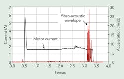
The OLTC monitoring technology uses a current clamp meter on the OLTC motor power supply in the transformer cabinet and a vibro-acoustic sensor on the OLTC tank, as close as possible to the OLTC diverter switch. The measured current is used to trigger a tap change measurement. Once the measurements have been recorded from the two sensors, digital signal processing and high-level data processing are performed on both signals, leading to the diagnosis. The tap position and OLTC temperature also are recorded for each tap change because these parameters affect the measurement.
Several parameters can be used to detect any significant changes that could be related to a faulty condition. These parameters make it possible to check operating times, current amplitude and profile (particularly the inrush current), delays between motor start and switching, and switching time. Detailed analysis of switching vibrations also makes it possible to identify the amplitude and duration of impacts caused by the separation and closing of switch contacts.
The monitoring methodology is based on two levels of diagnosis: the first detects any significant change in the measurements while the second provides a more detailed condition assessment that can be related to a possible faulty condition (for example, contact wear, contact alignment, arcing and motor drive problems).
The advantages of vibro-acoustic technology applied to the diagnosis of the OLTC condition include the detection of a wide range of OLTC problems and nonintrusive monitoring with sensors installed on the outside of the OLTC.
The development of trend algorithms and the possibility of comparing the results to previous measurements on the same unit greatly improve the condition assessment accuracy in real time. Continuous monitoring offers additional benefits:
- Real-time diagnostics in real operating conditions
- Improved sensitivity compared to periodic testing
- Identification of problems caused by rapid degradation
- Correlation of diagnostics results with other data available at the substation (for example, load and temperature).
Field Experience
Two OLTC monitoring prototypes were installed in February 2010, and some 23,000 tap changes have been monitored to date. An analysis of the measurements was performed to characterize the OLTC behavior in field conditions and lay down the requirements for the development of a robust and reliable automatic monitoring algorithm.
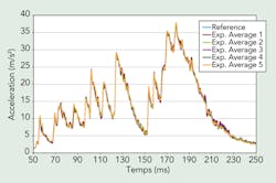
The monitoring algorithm is based on short-term and long-term variations to detect the various possible types of failure modes. Averaging and time-realignment techniques reduce the natural variations between the acoustic signatures of a tap changer in good condition. The temperature influence is taken into account because the total switching time at low temperature can be extended by more than 10%, which could be interpreted as a faulty condition. The technique has been successfully applied on new vacuum-type OLTCs and an excellent repeatability of the measurements has been demonstrated.
New Bushing Monitor Technology
Conventional periodic off-line electrical insulation diagnostic tests (at 10 kV) show a limited ability to prevent or detect incipient transformer bushing failures. The on-line diagnostic approach has the advantage of evaluating the insulation at full voltage and service temperature. Moreover, since the measurement is done continuously while the transformer is in service, the diagnostic performance is improved for problems with a short gestation period.
Field experimentation of methods used to derive parameters related to the electrical insulation — that is, the capacitance and power/dissipation factor from on-line measurements of the bushing tap current — clearly shows a comparison of measurements on bushings connected in parallel on the same electrical phase is more sensitive than the sum current method or any interphase-based calculations.
The common technology used to implement such measurements requires galvanic links between the bushings under examination and a central measurement system, as the signals from the bushing taps used to determine the phase angle must be recorded synchronously. The cabling required for this distributed measurement increases the implementation costs and, therefore, limits the application of this technique to monitoring bushing insulation in a large transformer population.
To resolve this issue, IREQ developed a new concept of distributed measurements using GPS receivers to provide time synchronization. This reduces the implementation cost of the technology (no cabling required between transformers) while maintaining the required measurement accuracy.
These measurements require highly sensitive equipment because a phase shift of roughly one-tenth of a degree between two bushings could indicate the presence of a fault in one of the monitored bushings. High sensitivity is even more important when monitoring bushings at very high voltage because these are made up of a large number of capacitive elements in series (for example, about 100 in series for 735-kV bushings).
New Distributed Measurement System
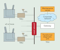
The decentralized system consists of a transformer monitoring unit (TMU) that transfers GPS time-tagged measurements to the transformer diagnostic unit (TDU) using the existing substation yard communications network.
The TMU is connected to the transformer bushing tap sensors and installed in the cabinet. The TMU input also can be configured to measure a reference signal on a voltage transformer. A GPS antenna is attached on the TMU’s timing receiver. The TDU, located in the substation control building, receives the phasors from the TMU, computes the Dtand and amplitude ratios, stores data, makes trending analyses, makes a local diagnosis and sends alarms to the monitoring center.
The modular approach of the system allows the user to combine any pairs of monitored equipment in a substation using the TDU’s configuration manager, thereby allowing maintenance personnel to explore and analyze the data remotely.
Field Experience
The installation was done on three banks of single-phase 735/230-kV, 370-MVA auto-transformers connected in parallel (nine units). The daily variations in the decentralized system were similar with a slightly higher instantaneous dispersion that demonstrated good performance in field conditions with the new technology compared to a standard galvanic measurement system.
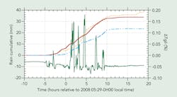
The typical daily stability of Dtan measurements appears to be better than 0.05% except for special events like grid commutations or rain. In both cases, the Dtan value is disturbed during the event, and the baseline may stabilize at a slightly different value, representative of the new operating conditions (for example, transformer temperature or cleanliness of the bushing). Similar dynamic transitions also are observed for the amplitude ratios.
The monitoring system captured many rainy events during field trials. Weather data was collected from three weather stations, and it was noted that the Dtan fast fluctuations exceeded 0.15% during rain, but the baseline fluctuation was in agreement with the usual one-day period fluctuation.
Therefore, filtering of ambient conditions is an important aspect to be considered in the bushing diagnostic algorithm. The proposed filtering algorithm is based on local temporal stability of the estimated measurement from the standard deviation over several successive estimations of Dtanδ. A measure is considered invalid when the standard deviation exceeds a threshold level. This threshold level can be fixed manually or automatically based on statistical analysis of previous measurements.
Condition Monitoring Information
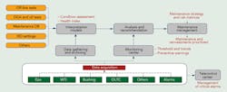
Implementing monitoring technologies offers new possibilities for transformer operation and maintenance. The traditional approach is to route alarms and monitoring data solely to the control center, which relays the information to facility managers when warranted. In the new approach, only critical alarms continue to be routed to the control center, while the remote maintenance center uses algorithms to generate preventive warnings. The remote monitoring center has all of the transformer status information needed by technical support staff to diagnose a problem and recommend corrective maintenance to the facility manager.
Another important aspect of the monitoring project is to provide condition indicators that will be used to prioritize reinvestments and maintenance. Hydro-Québec uses risk matrices to optimize its activities. To prioritize transformer reinvestments and maintenance resources, a condition indicator, or health index, is generated from data in the various databases. Transformer monitoring data collected by remote monitoring centers will make it possible to update this information more quickly and, in some cases, provide additional detail.
Improve Condition Assessment
IREQ has developed new technologies to monitor OLTCs and bushings because these transformers are at the origin of two-thirds of major failures in Hydro-Québec’s transmission system transformer population. Now available for transformer OLTCs and bushings, these on-line monitoring technologies, which have been subjected to extensive field testing, will help to prevent major failures by early detection of incipient faults.
They also will reduce maintenance costs and improve transformer availability as some off-line tasks (for example, bushings power factor tests or oil sampling) will no longer be required. Periodicity for OLTC internal inspection also can be extended based on the on-line monitoring diagnostics.
The diagnostics from these new systems are integrated into Hydro-Québec’s information technology model to complete the existing data and improve the global assessment of a transformer’s condition. These new technologies will contribute to the utility’s efforts to cope with an aging transformer population and improve condition-based transformer maintenance.
Acknowledgment
The work described in this article was made possible by the contributions of the following IREQ, Hydro-Québec team members: Michel Gauvin, Sylvain Riendeau, Francois Léonard, Louis Dupont and Jean Goulet.
Patrick Picher ([email protected]) graduated from Sherbrooke University, Canada, in 1993 with a BSEE degree and received a Ph.D. degree from École Polytechnique de Montréal, Canada, in 1997. Since 1999, he has been working as a researcher and project manager at Hydro-Québec’s Research Institute (IREQ), where his research interests include transformer modeling, diagnosis and monitoring. Picher is an active member of various CIGRÉ and IEC working groups, and he is currently secretary of CIGRÉ Study Committee A2 – Transformers.
Claude Rajotte ([email protected]) graduated from the École de Technologie Supérieure in Montréal, Canada, and initiated his career at Hydro-Québec’s Research Institute (IREQ), where he focused on research activities related to electrical apparatus diagnostic techniques. In 1990, he joined the Hydro-Québec substation maintenance department, where he works in maintenance practices and strategies, apparatus diagnostics, monitoring and database systems, and research and development. More recently, Rajotte has been working on transformer specifications, design reviews, remaining life assessment and technical support for transformers. He is a member of the Ordre des Ingénieurs du Québec (P. Eng.) and chairman of CIGRÉ Study Committee A2 – Transformers.
Company mentioned:
Hydro-Québec | http://www.hydroquebec.com
