Ever since the French pioneer, Lucien Gaulard, built the first power transformer, the voltage and power levels of AC transformation have progressed. The underlying physical principles, however, remain virtually unchanged. The power electronic transformer is about to change all this. Medium-frequency transformation is on the verge of opening a new era in AC to DC and DC to DC conversion with enhanced efficiency and a low environmental footprint. Thomas Edison's dream of making a DC-DC transformer has finally come true.
The rolling stock challenge
In rolling stock, the weight of on-board equipment is a major constraint facing train manufacturers. Traction transformers are no exception. In addition to weight, noise emissions, efficiency, safety, fire and smoke compliance must all be considered. Traditionally, measures taken to save weight in rolling stock transformers were paid for by poor efficiency. Power or current density needs to be much higher than for stationary power and distribution transformers, and thus higher copper losses are accepted as a necessary compromise. As basic technology has not made great advances since 1884, state of the art traction transformers have reached the limits of physics and no major further improvement in efficiency is to be expected. Or is it?
The size of the magnetic core of the transformer is linked to the operating frequency. The core size, in turn, influences the radius of the windings and the amount of copper used. The amount of copper is directly proportionate to the losses. A reduction in transformer size that does not compromise efficiency must thus address the size of the core. This means acting on the frequency. The grid frequency is, of course, given. Thus the only way is to act is on the local frequency.
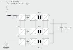
1 PETT principle with its N Medium Frequency Transformers (MFT1 to MFTN)
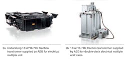
From this train of thought emerged the concept of the PETT (power electronic traction transformer) ➔ 1. Power electronic conversion raises the frequency to several kHz, and allows a major reduction in transformer size. Compared to conventional traction trans- formers, medium frequency transformation utilizes less copper, less iron and less or no oil ➔ 2. Simultaneously, power density and efficiency are drastically improved ➔ 3.
2 Low frequency traction transformers
|
3 ABB pioneers breakthrough rail innovation ABB has successfully developed a revolutionary traction transformer that uses power electronics to reduce its size and weight while increasing the energy efficiency of the train. The new power electronic traction transformer (PETT) is based on an innovative, multilevel converter topology that uses IGBT (insulated gate bipolar transistor) power semiconductors and medium frequency transformers replacing the conventional transformers and inverter combination. In addition to its weight and size advantages, the new power electronic traction transformer helps improve efficiency and reduces noise levels. The innovation is a breakthrough that achieves one of the rail industry's priority objectives of reducing the weight of on-board components. The traction transformer, which is traditionally made if iron and copper, is one of heavy pieces of equipment on a train. Size is another challenge for traction transformers, because reducing the amount of space used by equipment means that more space is available for paying passengers. Over the past decade, ABB has continually made design improvements in rail components, creating compact products like roof-installed transformers that reduce equipment footprint without compromising performance. The innovative use of power semiconductors in a core component such as traction transformers opens up new opportunities for rail markets around the world, and should be extendable across a range of other applications. |
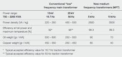
Typical comparison power density figures are shown in ➔ 4. The table illustrates how the power density of the traction transformers increases mostly linearly with the frequency.
4 Power density and other key figures for low and medium frequency transformers
Technical challenge of the MFT
Increasing the operating frequency to decrease the size of the transformer would seem to be a simple approach whose implementation might appear straightforward. In practice, things are not as simple. Many aspects differ from conventional low frequency technology and the development of the PETT had to overcome these.
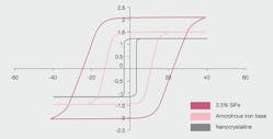
Core losses depend on the material the core is made of. When a magnetic field is applied to a ferromagnetic material, a modification of the material structure occurs (alignment of magnetic domains as function of temperature, composition of the material, etc.). This modification changes the properties of the material, notably its permeability, hence the well known hysteresis loop of magnetic materials. The area inside this loop defines the core losses at the considered operating frequency ➔ 5.
5 Typical B-H loop for 3.5 percent SiFe, Amorphous and nanocrystalline magnetic materials
Methods used to change the material properties and the related losses include material composition, amount of impurities, grain orientation, thickness and laser scratching. In a traditional traction transformer, 3.5 percent Silicon Steel (SiFe) sheets of various grades are used. The thicknesses are in the range of 0.2 to 0.35 mm and the saturation induction level can be up to 2 T. The core losses are usually given in the range of 1–2 W/kg at 1.7 T and 50 Hz. When these materials are used at higher frequencies, the losses increase notably and can reach up to 50 W/kg at 1 T and 1 kHz. Such materials are obviously not suitable for high frequency ranges.
New materials such as 6.5 percent SiFe, Nickel Steel (NiFe) alloys, amorphous or nano-crystalline are available and suit high frequencies (10 kHz – MHz range). Properties of these materials vary, and the choice is be driven by design targets. The different materials suitable for high frequency are available in powder form or in steel tape form. The thicknesses of the steel bands are in the 20–35 μm range, and their production requires very specific tooling. The saturation induction is between 0.5 and 1.5 T. The inherent losses vary strongly with the induction level and the operating frequency ➔ 5.
For the copper, high frequency currents mean higher proximity and skin effects and thus higher resistance or lower effective copper section. There are several ways to counteract these phenomena. Hollow conductors (tube type winding) or Litz wires are two possible answers. The Litz wire (named after its inventor) is a strand type wire where each single small copper conductor is insulated. Choosing the right strand size allows a reduction of AC losses to an acceptable level, but the filling factor of Litz wire increases the DC losses, since the effective copper section is reduced in comparison to a full solid conductor.
Using a reduced core and winding size, the weight and loss reduction targets are achievable. In the railway sector, the different AC network voltages vary from a few kV up to 50 kV (mainly 15 kV / 16.7 Hz and 25 KV / 50 Hz). One of the main tasks of a traction transformer is to supply the galvanic isolation between the overhead line and the traction motors. In the PETT, the medium frequency transformer must fulfill this function. According to railway standards, the requirement on the dielectric insulation level can be up to 77.6 kVrms. The minimum size of the transformer is thus no longer defined by the core and winding size, but by dielectric requirements. The limit depends on the assembly type, the insulation material and the design selected for the transformer.
The mission profiles on thermal cycling for a traction transformer are usually very restricting. One million cycles for a traction transformer life is not unusual. Thermal cycling and high electric field are important stress factor for the insulation material.
Cooling is of extreme importance. Even if efficiency is high, the small size of the transformers increases the power density and at the same time the density of losses. Efficient and compact cooling methods are required. In addition, the transformer is no more a stand-alone device but must interact with its surrounding power electronics. A two phase medium, tap water or air are possible choices to ensure adequate cooling. Compatibility with power electronics cooling medium is of course a prerequisite.
6 Size and footprint comparison of power transformer units of equal ratings
ABB's answer to the MFT challenge
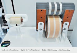
ABB is currently working on three different types of insulation materials: air, oil, resin. For each type of these, specific design rules are considered. Matching all the above ingredients and design rules, ABB will soon be ready to offer a large variety of medium frequency transformers suited for various applications ➔ 6, 7.
It is notable than above a certain frequency level, the size reduction or power density increase ceases to be relevant. Doubling the frequency from 5 kHz to 10 KHz does not result in a doubling of the power density but only a 30 percent increase. The reason lies in the insulation requirement, whose influence rises with the frequency compared to the size of the core and coil. The overall dimensions are no longer dictated by the frequency but a new physical limit: the insulation distances.
High insulation levels, small size, high efficiency, easy to cool will be the hallmarks of ABB's response to the medium frequency transformer challenge.
Toufann Chaudhuri
Christian Vetterli
ABB Sécheron SA
Geneva Switzerland
[email protected]
[email protected]
