Germany Addresses the Renewables Challenge
The large share and massively increasing amount of distributed generation — predominantly wind and photovoltaic resources — is setting new challenges for distribution system operators. Huge investments in grid infrastructure are needed to ensure capacity for integrating these resources into the grid. Grid operation and monitoring become more complex because power flow becomes less predictable.
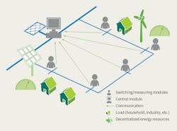
In Germany, medium-voltage networks hardly have any monitoring facilities and grid automation installed. To address the development, implementation and field testing of remote-controlled switchgear and a grid control system at the medium-voltage level, a large-scale German demonstration project was funded as part of the European GRID4EU smart grid project. For the demonstration, a multi-module system (MMS) was implemented that focuses on the interaction between monitoring modules installed in select secondary substations and a small control center located in the primary substation. The decentralized modules are divided into measuring modules that provide field measurements and switching modules that perform field measurements as well as execute the switchgear.
The control center and modules each are equipped with a remote terminal unit (RTU). The MMS is supplemented by a general packet radio service (GPRS)-based communications infrastructure to ensure interaction between all components. The remotely controlled switching facilities provide the possibility of dynamic topology reconfiguration, a new concept in the operation of medium-voltage networks.
For safety reasons, the modules are equipped with a service modus (that is, deactivation of the switchgear and remote control to permit maintenance work on the grid). If service or maintenance work is in progress, the earthed parts of the grid remain earthed and all modules are isolated and non-operable.
Multi-Module System
The MMS was designed for three different operational case studies. The first is decentralized grid operation in medium-voltage networks to avoid overvoltage and overcurrent conditions. Based on the readings of the measuring modules, the current network status can be detected by the MMS. When an overcurrent or an overvoltage is detected, the reconfiguration starts automatically by shifting one or more of the network open separation points. The overall load flows are changed as a result of the network topology reconfiguration. With this reconfiguration, the utility can avoid moving overloaded equipment and voltage-constraint violations.
The second is failure management on the medium-voltage network. If an outage occurs, the MMS limits the affected section of the network based on the information from the remote short-circuit indicators. Subsequently, the faulty section of the medium-voltage network is isolated by automated switching operations from the rest of the network. Finally, the automated reconnection of customers affected by the interruption of supply is initiated.
The third is a reduction in grid losses by reconfiguration to restore optimized grid operation. The volatility of decentralized energy plants and the dynamics of customer-load demands result in a continuous change of load conditions on the network. However, the state of the network is subject to continual change in accordance with the conditions established by the MMS. As a result, the network power losses are reduced compared to those applicable on a static network topology.
Westnetz Field Trial
The German demonstration project was initiated and implemented by innogy and Westnetz, the largest distribution system operator in the western part of Germany. The project was installed on the 10.7-kV network in Reken, located in North Rhine-Westphalia, Germany. This section on the medium-voltage network was selected for the field trial as there had already been a balance between the installed renewable energy resources and maximum demand.
Furthermore, an increase in the connection of renewable wind and photovoltaic energy resources was anticipated in Reken. The change in this area was typical for the German Energiewende — Germany’s energy transition to a low-carbon, environmentally sound, reliable and affordable energy supply — and provided an ideal platform for the field research in innovative solutions.
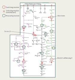
The medium-voltage network in the Reken area consists of approximately 120 medium-voltage and low-voltage secondary substations, of which 18 substations were selected for the field trial. Seven substations were equipped with 10.7-kV switchgear with remote-control facilities, and the remaining 11 substations were equipped with monitoring equipment. The substations equipped with new switchgear were located at crucial network nodes to ensure they would be subject to the maximum number of possible and necessary switching operations. Similarly, the monitoring equipment was installed in substations positioned in the medium-voltage network to achieve maximum monitoring with minimum equipment.
Hardware Implementation
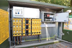
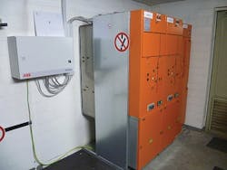
The medium-voltage switchgear and monitoring equipment are composed of a similar set of components. Depending on the current condition of the existing secondary substations, Westnetz had to deploy three different approaches to installing the new switchgear:
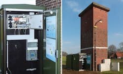
• Option 1: Install a switchboard adjacent to the existing substation
• Option 2: Replace the existing secondary substations
• Option 3: Replace the existing switchgear in a walk-in substation.
The first option was selected depending on the design of the existing substation. For example, in a tower substation that had insufficient space for the integration of the new switchgear, a complete replacement of the substation was unnecessary. The second option was selected to replace either time-expired substations or those close to the end of their lifetime, or if an existing substation needed to be relocated to a new position or updated by grid planning. The third option was selected when a substation had sufficient space without the need to interfere with the operation of existing network assets (for example, the medium-/low-voltage transformer or the low-voltage distribution panel).
The monitoring package in all substations consists of an ABB RTU from the RTU540 product line with measurement units (ABB 560CVD11, 560CVD03) and a power supply with battery backup. This is a standard configuration, known in Germany as flexible intelligent secondary substation automation (FIONA).
Communications Infrastructure
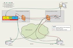
The necessary information and communications technology infrastructure was established to ensure communication between the central RTU in the control center with the supervisory control and data acquisition (SCADA) system and the central RTU with the decentralized RTUs in the substations equipped with the new medium-voltage switchgear and monitoring equipment.
The modules in the secondary substations send data through a GPRS connection to an access point name. The information is then forwarded to the central RTU through the backbone of Westnetz’s process data network. Finally, the central RTU collects all the data and provides them to the grid control system (SCADA).
All these information exchanges are performed on a hierarchical network based on the following communications structure:
• At the basic level, the transmission control protocol/Internet protocol (TCP/IP) data flow goes through a virtual private network (VPN) router located at the communications center.
• At the second level, the encrypted VPN provides the necessary cybersecurity to avoid any hijacking of the system from outside.
• At the third level is the dedicated modules network. As soon as the master RTU is connected to the VPN, logical IEC 60870-5-104 connections can be established between the modules and the master module as well as with the SCADA system. This is always initiated by the master or SCADA (controlling substation).
Decentralized Grid Operation
The core control algorithm for overload-driven switching operations runs centrally on the RTU in the primary substation, evaluating all local states from all modules. When a voltage or current limit violation is detected, it is forwarded to the central module as a trigger for the optimization routine. An optimal violation-clearing network topology configuration is suggested and a corresponding switching action scheme is applied.
For example, if the voltage of one monitored substation crosses the 10.7-kV level — which is defined as near critical, following the condition of exceeding a preset time period — then the algorithm is activated. Finally, switching to another topology improves the voltage behavior and puts the system in a secure state. The single operational steps of the control system behavior are as follows:
1. Simulation begins
2. Secure voltage state is left
3. Control algorithm activates
4. Optimization process starts
5. Optimization finishes, switching sequence is written, execution activates
6. Switching process starts
7. Switching process finishes
8. Simulation ends.
The switching process consists of one switch closing and one opening command. It is notable that the entire process, from detecting a problem until its elimination (steps 1 through 7), typically takes about 1 minute to 5 minutes, which is considered an adequate reaction time. This time period includes the optimization runtime and the switching process, consisting of the switchgear reaction times and idle times for successful switching notifications.
Impact on Network Reliability
The positive impact of the MMS was analyzed by comparing the typical network reliability indices — the system average interruption duration index (SAIDI) and average system interruption duration index (ASIDI) — before and after the system implementation. Both of the reliability indices were almost halved for the demonstration area in Reken. Use of the MMS has resulted in shorter outage times over the complete network. Moreover, the limited number of switchgear units with remote operational facilities was sufficient to increase the reliability of the medium-voltage network substantially.
The installation of remote-controlled medium-voltage switchgear combined with measuring modules on a typical medium-voltage network can ensure optimum operation at all times, thereby improving network reliability and minimizing network losses. This solution is particularly useful for medium-voltage networks with a high penetration of distributed energy resources and can be used to defer traditional network expansion as well as reinforcement projects to enhance the quality of supply.
Acknowledgement
The authors wish to acknowledge the support and assistance given by Anna Carina Schneider with Westnetz and Peter Noglik with ABB A.G. in the preparation of this article. ♦
Lars Jendernalik is responsible for the technical services of Westnetz, the largest distribution system operator in Germany. Previously, he worked in several asset management positions for more than 10 years. He has been involved in distribution systems, the grid integration of decentralized energy resources, and especially the development of asset management, grid planning and grid operation for more than 15 years.
Thomas Wiedemann is manager of the new technologies department within innogy SE, which is part of the RWE Group. As head of the Center of Competence Energy Grids, Wiedemann is responsible for the group-wide research and development project portfolio for distribution grids.
Anton Shapovalov is a research associate at the Institute of Energy Systems, Energy Efficiency and Energy Economics (ie3) at TU Dortmund, a German university. He received his diploma degree in electrical engineering from TU Dortmund in 2011. His research interests are in field autonomous network operation and control algorithms.
Sidebar: The European GRID4EU Project
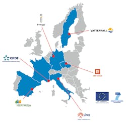
GRID4EU was an innovative smart grid project proposed by a group of six European Union (EU) distribution system operators in close partnership with a set of electricity retailers, manufacturers and research organizations. Planned for the 51-month period from November 2011 to January 2016, the project adopted a systemic approach to test in place, on existing operational networks, innovative concepts and technologies. The project aimed to highlight and help to overcome some of the barriers to smart grid deployments, whether technical, economic, societal, environmental or regulatory.
The main focus of the project was on how distribution system operators can manage electricity supply and demand dynamically, which is crucial for the integration of large amounts of renewable energy as well as to empower consumers to become active participants in their energy choices. Whereas most of the demonstration projects on smart grids focus on a very specific area, the GRID4EU project involved a large set of smart grid solutions (multi-systems approach) under several boundary conditions (multi-sites approach).
The project was structured to consider the following challenges:
• Existing networks are made of long-life assets and equipment that cannot be removed or easily upgraded.
• In Europe, the technical, economical, societal and regulatory context for distribution grids significantly varies according to each countries’ specificities.
To take these constraints more into consideration, the project was organized around large-scale demonstrators located in six EU countries. The locations were chosen to provide various boundary conditions, whether related to grid characteristics, regulatory aspects or weather conditions.
The final report for GRID4EU was published online in 2016. The report showcases and summarizes key results of GRID4EU. In addition to highlighting technical outcomes, it also encompasses results on transversal activities (scalability and replicability analysis and cost-benefits analysis), soft learnings, and environmental and social aspects.
Check out the October 2017 issue for more articles, news and commentary.
About the Author
Lars Jendernalik
Lars Jendernalik is responsible for the technical services of Westnetz, the largest distribution system operator in Germany. Previously, he worked in several asset management positions for more than 10 years. He has been involved in distribution systems, the grid integration of decentralized energy resources, and especially the development of asset management, grid planning and grid operation for more than 15 years.
Thomas Wiedemann
Thomas Wiedemann is manager of the new technologies department within innogy SE, which is part of the RWE Group. As head of the Center of Competence Energy Grids, Wiedemann is responsible for the group-wide research and development project portfolio for distribution grids.
Anton Shapovalov
Reasearch Associate
Anton Shapovalov is a research associate at the Institute of Energy Systems, Energy Efficiency and Energy Economics (ie3) at TU Dortmund, a German university. He received his diploma degree in electrical engineering from TU Dortmund in 2011. His research interests are in field autonomous network operation and control algorithms.
