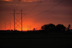
In July 2016, a storm with high winds hit the Twin Cities area, about 30 miles (48 km) northwest of Minneapolis, Minnesota, U.S. After the storm passed, repair crews found multiple distribution lines blown down. Out in the countryside, two 8.5-mile (13.7-km) parallel sections of 345-kV line — with 54 H-frame structures on each line — were on the ground in what was clearly a cascading failure. Fortunately, the dead-end structures contained the cascade.
The distribution damage was quickly repaired, and — thanks to the hard work of Xcel Energy employees, crews and contractors — both transmission lines were rebuilt and back in service by the end of December 2016.
Wood Works
The two transmission line sections are 100 ft (30.5 m) apart and run between the Minneapolis suburbs of Maple Grove and Rogers. The terrain is primarily wetlands, ponds, marshes and agricultural land. The transmission lines carry power from substations near Xcel Energy’s Monticello and Sherco power plants.
As soon as the storm passed, Xcel Energy and its regional transmission authority began deciding which transmission line needed to be rebuilt first. The construction department was involved to determine how fast rebuilding could start.
Thanks to added redundancy on the grid — created by several large capital transmission projects built over the last five years — power still could be transmitted around the damaged lines, so the rebuilds were considered important but not an emergency. However, there was an urgency to restore one of the two lines as quickly as possible to help with system reliability and redundancy. Therefore, wood construction was chosen to rebuild the Monticello line based on material availability and past experience with wood construction in these wet conditions.
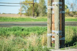
Because of the terrain and soil conditions, everyone knew the project was going to be difficult. The failed H-frame structures were installed in 1971 on wood pile foundations. Large wood poles were driven into the ground until they hit soil with sufficient strength to support the H-frame structures. The piles were then banded together and the aboveground structures were built. Some of those piles were driven 50 ft (15.2 m) into the ground. The utility expected supporting the new H-frame structures in the deep, peaty soil was going to be a challenge.
As there were enough wood poles on hand to rebuild the Monticello line, Xcel Energy decided to go forward with wood replacement. Because the Sherco line rebuild could wait, the engineering department had time to explore other options for its replacement.
Steel and Helical Piles
While work began on the Monticello line, engineers reread reports and sifted through papers and brochures. Steel towers sounded like a good approach for the Sherco line. Also, helical pile foundations were a design option the engineering team wanted to consider.
The driving consideration was the prevention of possible future cascading failures. Reports indicated steel poles were better at preventing cascading failures. If another powerful storm occurred in the future, although it might take out the wood line, engineering wanted it to be unlikely that both lines would fail.
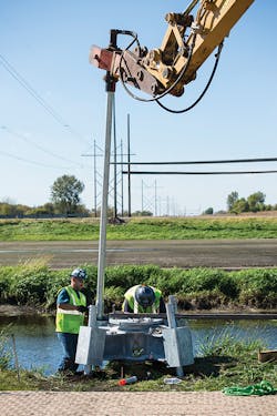
The second problem to address was the piles. Driving wood poles into wet, peaty soil takes time and big equipment, which has a significant impact on the surrounding environment. Helical piles can be screwed into the ground quickly with a special drill head on a small backhoe, minimizing environmental impact.
Among the vendors with helical solutions was Hubbell Power Systems (HPS), which had recently provided Xcel Energy information on its helical solution. Two Xcel Energy principal engineers, Jeff Gutzmann and Tony Moore, contacted HPS and continued to examine alternatives. Ultimately, CHANCE helical anchors and quadrupod grillages were used on the Sherco line.
Marshes and Matting
Xcel Energy had several reasons for using helical piles. First, while there was some historical information from the original build, there was no detailed soil information for each tower location. But because soil conditions varied so much over the length of the rebuild, the utility needed a solution that would work anywhere, even in deep peat. Helical piles would do that. Engineers could calculate the necessary installation resistance and installation crews would install the piers to specification.
Second, the utility wanted to minimize the impact construction would have on the wetlands and agricultural land. Work took place during the growing season in the summer and fall of 2016, and the utility sought to reduce any damage to or interference in the fields. Helical piles could be screwed into the ground quickly, while wood piles would have to be pushed into the ground with a backhoe, sometimes by being vibrated into the ground with a special attachment to the backhoe.
Matting also was a significant issue. To prevent damage to the land and keep vehicles from getting stuck in the mud, matting was required any time a vehicle had to cross wet ground or farmland. Since most of the right-of-way is boggy, there are many drainage ditches and drain tiles under the ground. (Farmers use drain tiles to direct ground water from their fields.) Also muddying the waters was the fact that 2016 was an extremely wet season, which raised the water table to almost ground level. This resulted in contractors matting into most, if not all, of the structures.
Putting mats down is expensive, but helical piles can be installed with much smaller equipment and that translates into significantly less matting. This lowers costs and reduces field impact, which is especially important on agricultural land. As it was, crews used nearly 7800 polymer mats to ensure safe access to the structure sites.
The helical piles were a quicker, better and more economical solution for the Sherco line. Additionally, HPS helped to locate local contractors with experience installing the piles.

Sharing the Engineering
Engineering the design was a collaborative effort. Jeff Gutzmann worked with HPS on the helical pile design. The final design called for four piles per foundation, each with five helicals — one at 10 inches, one at 12 inches and three at 14 inches (254 mm, 305 mm and 356 mm, respectively). Depths varied from pile to pile and location to location but were typically between 25 ft to 35 ft (7.6 m to 10.7 m). Xcel Energy’s construction department selected a contractor with prior experience working with CHANCE helical foundations, and the contractor purchased and installed the specified piles from HPS.
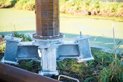
Once the piles were driven into the ground, a grillage was attached to the top and grouted into place. The grillage is like a cap. It is welded together, and there are holes for the tops of the helicals. These are filled with grout to hold down the grill and a baseplate. The grouted pockets were used to create a moment connection between the piles and the grillage. HPS designed the grillage and an Xcel Energy engineer inspected the material as it arrived, checked the welding and oversaw the installation.
As work began, Xcel Energy principal engineer Brad Hill identified a problem that required the grillage to be modified. Hill visited the HPS manufacturing plant in Centralia, Missouri, U.S., and worked with HPS to modify the design. After that visit, there were no further issues. Overall, the result of using the helical pile foundations was excellent. The base section of the steel shaft had a base plate welded to it and the grillage had a flange plate welded to it, which allowed for a bolted connection between the grillage and the shafts. PLS-CADD was used to create the above-grade designs and specify the steel poles.
Timetable
The storm took out the Xcel Energy structures in early July 2016, and the first line was returned to service on Sept. 1. Xcel Energy started designing the second line and working with HPS at the end of July. The contractors began work in late September when the steel poles began to arrive. All belowground work and grillage was completed by mid-October 2016, and the line was energized in December 2016. In total, Xcel Energy replaced 108 structures and 718,080 ft (218,871 m) of conductor, shield and optical ground wire.
Within Xcel Energy’s service territory, there are a lot of wet locations. The helical pile foundations are a solution Xcel Energy will use again in a similar situation. The cost of this second line was competitive with the cost of using wood, and it was a fast, easy installation that minimized the project’s environmental impact.
Acknowledgement
The author appreciates the assistance of Gary Seider, engineering manager of civil and construction projects at HPS, in the preparation of this article.
Matthew Hoese is an engineering manager at Xcel Energy and project manager for transmission line design projects up to 345 kV. He leads his team of engineers, designers and support staff through all phases of a project life cycle to produce high-quality transmission line designs and construction packages, while keeping the project schedule and budget in the forefront. Hoese is a licensed professional engineer.
Sidebar: The Importance of Soil Testing
To properly design a foundation or pile, two things must be examined, the geotechnical capacity (soil) and the structural capacity (foundation). It is common to start with the geotechnical capacity because, generally, the owner provides the load requirements for whatever the application is — transmission towers, buildings, retaining walls and so forth. Analysis of the ground conditions is necessary to design a foundation or pile to meet those needs.
To get the geotechnical data, the soil must be tested. The analysis reveals a number of things, but one of the most important is its ability to support load. For fine-grained soils, like clay, strength categories start with very soft and increase to medium, firm, hard, stiff and very stiff. For coarse-grained soils, like sand and gravel, the categories include very loose, loose, medium dense, dense and very dense.
The second factor to consider is depth. Different soil layers beneath the surface can have significantly different characteristics. The strength of the soil and depths dictate the foundation design. If helical piles are used, it also dictates the number and sizes of the helical plates.
In the case of the Xcel Energy line rebuild, the top 10 ft (3 m) of soil was peat and clay. It was very soft and not a good support for new steel towers. Below that, the soil got stiff pretty quickly. Most of the helical piles were 25 ft to 35 ft (7.6 m to 10.7 m) long and extended down far enough into load-bearing soil to support the load.
Even if the bottom layers of soil have load-bearing properties, the top layer cannot be ignored. If the top layer is soft, lateral loading must be considered to determine whether there is a potential for the pile shafts to buckle. If the soil is soft, the pile materials must be adjusted and sized to increase stiffness, rigidity and resistance to lateral forces.
Testing
The most common type of testing is called a sounding, or boring. Drillers attach a continuous flight auger to the rig. They drill a hole and take samples at different depths. This can be done dry or, if the water table is high, a slurry or drilling mud can be used to prevent the hole from caving in or filling up with groundwater.
The standard penetration test (SPT) is another option, per the ASTM D1586 standard. A hole is dug, typically in 5-ft (1.5-m) increments, and a hollow split spoon is attached to the drill shaft and lowered into place. Then a 140-lb (63.5-kg) hammer is raised and repeatedly dropped 30 inches (762 m) until the sampler is driven a specified distance into the ground, usually 18 inches (457 mm). The total number of blows for the last foot of penetration is the N value of the SPT, and it can vary significantly. For very dense soil, the blow count can be more than 50 blows. In soft clay, the blow count might be one or two.
Cost
Soil tests should be considered for any foundation but are particularly important for deep foundations — 5 ft to 7 ft (1.5 m to 2.1 m) belowgrade. Costs vary, depending on the region. A single boring, which requires a drilling rig, can cost about US$1500 in the Midwest and $4000 in the Northeast. Because mobilizing and transporting the rig is a major part of the cost, multiple samples taken at one site cost proportionally less. ♦
About the Author
Matthew Hoese
Matthew Hoese is an engineering manager at Xcel Energy and project manager for transmission line design projects up to 345 kV. He leads his team of engineers, designers and support staff through all phases of a project life cycle to produce high-quality transmission line designs and construction packages, while keeping the project schedule and budget in the forefront. Hoese is a licensed professional engineer.