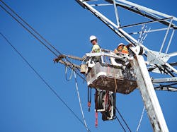
In 2008, the Public Utility Commission of Texas (PUCT) established a program to enhance the transmission system and to encourage the continued development of wind energy resources in West Texas. The Competitive Renewable Energy Zones (CREZ) program included more than US$5.9 billion in transmission construction projects. The PUCT selected Cross Texas Transmission (CTT) to design, construct and operate several of these projects in the panhandle of Texas.
With 235 miles (378 km) of new transmission lines to route, design and construct — not to mention a 345-kV switching station and a 345-kV series compensation station — CTT had a tremendous opportunity and several extraordinary challenges on its plate. CTT selected Burns & McDonnell to perform routing and engineering design for the transmission lines as well as EPC construction of the switching and series compensation stations.
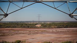
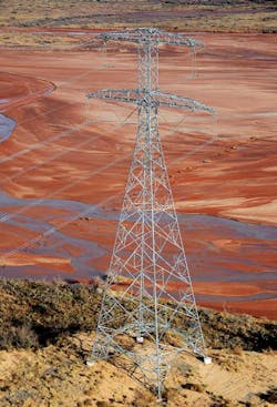
The project team started from a blank slate as it developed practices and designs, including conductors, hardware, loading criteria, structures and foundations. Any major undertaking is bound to face hurdles, and the CTT transmission lines were no exception. Among those challenges were some very long spans to clear pivot irrigation systems, canyons and stream crossings. But by far, the biggest of these challenges was the 0.5-mile (0.8-km) crossing of the Prairie Dog Town Fork of the Red River.
Defining the Challenge
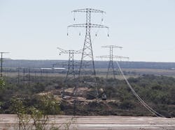
This crossing would be roughly parallel to an older wood H-frame transmission line that included two H-frames constructed in the riverbed, so placing new structures in the river bed was considered. However, there were two main challenges. The first was the potential for poor soil conditions and the subsequent challenge of constructing foundations and structures at this location. That would not be easy, but undoubtedly it could be accomplished. The second challenge was getting needed permits to place these structures in the riverbed. After some discussion with the regulatory authorities that controlled the river, CTT decided to take that option off the table. Basically, the authorities didn’t want structures in the riverbed, and getting the necessary permits would represent a major challenge and potentially cause schedule delays.
Since it was thus necessary to span the river, the team selected the best locations for structures on each side of the river and began designing the section. The resulting clear span between crossing towers was approximately 2,400 ft (732 m). The team quickly discovered that spanning the river with the aluminum conductor steel-supported (ACSS) Falcon conductors chosen for the majority of the project would require increasing the height of both crossing towers to well over 200 ft (61 m), which would lead to Federal Aviation Administration (FAA) permitting and lighting requirements. While this was certainly doable, the Burns & McDonnell team began to look at options that would spare CTT from the additional time and expense of that process and those requirements.
The other obvious solution was to reduce the conductor sag in this crossing span sufficiently to maintain structure height requirements of less than 200 ft. The team investigated three high-temperature, low-sag conductors that might accomplish this: ACSS/HS285, aluminum conductor composite core (ACCC) and aluminum conductor composite-reinforced (ACCR).
The Burns & McDonnell team contacted the conductor manufacturers associated with each of these options to make sure it selected the most appropriate conductor for its electrical requirements and to obtain the correct wire files for PLS-CADD modeling. Then the engineers completed crossing span designs for each conductor to determine the structure height requirements to achieve the desired clearance. Ultimately, this would guide the selection of the conductor for the river crossing.
Comparing the Candidates
To provide a point of reference, consider the ACSS Falcon conductor used for the majority of the transmission line. To achieve the desired clearance, towers with aboveground heights up to 235 ft (72 m) were needed. This clearly would not be sufficient to avoid FAA involvement.
The ACSS/HS285 conductor is a traditional ACSS conductor but with a higher-strength steel core to allow for higher tensions. To to achieve the desired clearance, towers with aboveground heights up to 205 ft (62 m) would be needed, nearly sufficient to achieve the goal of remaining below the height that would trigger FAA requirements but not quite good enough.
The ACCC conductor is similar to ACSS in that it has annealed aluminum strands, but with a carbon/glass composite core. For this conductor, an “ACCC Lapwing” was used because a Falcon equivalent ACCC conductor was not available at the time. To achieve the desired clearance, towers with aboveground heights up to 210 ft (64 m), which was even taller than what would be required for the ACSS/HS285 conductor, were needed to withstand heavy ice loads.
Finally, the ACCR conductor also uses composite technology, but with an aluminum composite core and aluminum zirconium outer strands. The ACCR Pecos conductor achieved the desired clearance with towers measuring 185 ft (56 m) of aboveground height, which was well below the threshold that would trigger additional FAA requirements.
And the Results Were
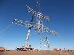
Based on these comparisons, CTT made the decision to use the ACCR Pecos conductor for the crossing span and one back span to a deadend tower on each side of the river. Revised load trees for the crossing towers were developed, allowing the tower manufacturer to design special river crossing structures for the additional loads. These river crossing tangent structures essentially ended up being the original lattice tangent tower designs with some selected member changes. The deadends were strengthened versions of the standard deadends to support the increased tensions. Minor changes to hardware assemblies were also made for this section to support the ACCR conductors.
These towers, assemblies and conductor were installed successfully, with minimal adjustments to the construction methods used to install the rest of the line. With the river crossed and without needing to involve the FAA, the team could turn its attention to other challenges on what proved to be a successful project that was completed on schedule and under budget.
Don Cannon is the transmission department manager for Burns & McDonnell in Houston, Texas, U.S. A member of ASCE and IEEE, he will be presenting more extensively on this project at the Electrical Transmission & Substation Structures Conference in September. He has a BSCE degree and a MSCE degree from the University of Tennessee.
