A steadily increasing demand for power has introduced a number of unique design and construction challenges within the overhead transmission sector, many of them environmental. The routing and siting process for transmission line construction is often extensive and time-consuming, requiring close coordination with numerous regulatory agencies. Although utilities strive to use existing rights-of-way (ROW), and are often successful, extensive alternate route analyses are typically required prior to gaining approval.
Environmental analysis of new routes or multiple routes can add significant time to the permitting process. Once routing and permitting have been approved, utilities and their consultants and contractors are faced with the challenge of constructing the alignment within the limitations set forth in each of the permits.
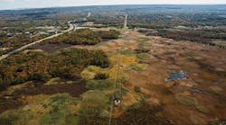
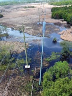
A portion of the new Susquehanna to Roseland Electric Reliability Project (SRERP) crosses Troy Meadows, a 3,100-acre (12,505-hectare) freshwater marsh located in Morris County, New Jersey, U.S. The area has been designated a priority wetland by the U.S. Environmental Protection Agency as well as a national natural landmark by the U.S. National Park Service. Within the protected area, the project scope included replacement of seven 230-kV lattice towers with seven new double-circuit 500-kV monopoles. Public Service Electric & Gas (PSE&G) coordinated closely with regulatory agencies and employed unique construction methods to ensure all construction was completed with minimal impacts to the wetland.
Access Restrictions and Challenges
Detailed studies were completed for three potential alignment routes as a portion of the project siting application. The New Jersey Board of Public Utilities concurred with PSE&G that use of the existing ROW was the preferred route for the new 500-kV SRERP. This route included traversing the Troy Meadows wetland.
The contractor preferred to use conventional foundations, but road building for transportation of the necessary equipment and materials would have required extensive temporary fill or timber matting. Temporary fill was rejected immediately for a variety of reasons. Timber mat roads were considered, but their impact, though temporary in nature, would have been significant.
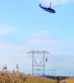
With conventional construction ruled out, the project team explored helicopter-supported construction as an alternative. The first challenge associated with this option was the feasibility of using a helicopter to set the monopoles, which had already been selected as the structure type for this portion of the project. Fortunately, the route through Troy Meadows did not include angle structures and allowed for lighter-weight, tangent monopole suspension towers to be used. However, at 190 ft (58 m) tall and weighing 150,000 lb (68,039 kg), the towers were still substantial.
Burns & McDonnell, PSE&G’s program manager for the project, worked with the monopole supplier and engineer to incorporate helicopter installation means into the design of the monopoles. This was accomplished by further segmenting the poles and incorporating innovative guide details into the flange-connected pole sections.
The second challenge was to select a foundation to meet the needs of the project. A comparative study was completed to determine the foundation type that would impose the least environmental impact and could also be constructed entirely by helicopter. Ultimately, micropile foundations were selected, and Burns & McDonnell worked with the T-line construction contractor Kh&m (a joint venture between Kiewit and Henkels & McCoy) to select a micropile foundation contractor.
Micropile foundations have been employed for numerous projects requiring helicopter construction techniques. They can be constructed with lighter-weight equipment and materials, making them conducive to light- and medium-lift helicopter transportation. Another benefit of micropile foundations over conventional foundation equipment is the compact nature of the smaller drilling equipment and the ability to minimize the total area of temporary and permanent disturbance.
With the unique capabilities to meet project schedule and other requirements, Kh&m selected Crux Subsurface to design and install the micropile foundations. The selection of a single specialty foundation contractor with numerous projects of similar design-build experience created the highest level of assurance of on-time completion for this project with an aggressive schedule.
Once it was determined helicopter support and micropile foundations would be employed, individual activities needed to be scheduled within a condensed project time frame. A bald eagle siting in close proximity to the ROW limited construction within Troy Meadows to a 106-day window, with just 60 of those days allotted for foundation work. This necessitated efficient collaboration among all parties involved.
Value Engineering
Prior to foundation construction, two rounds of value engineering were completed, effectively decreasing the number of micropiles and total disturbance area of the concrete caps. Reducing the required number of piles and amount of concrete significantly benefitted the project schedule.
The first round of value engineering looked at altering the original conceptual foundation design, which included larger-diameter micropiles using a bolted steel pile cap. By changing the cap material from steel to concrete, the fixity between the piles and cap was improved, and the field fit-up associated with the bolted steel cap was eliminated. The revision to the cap design led to a reduction in micropile diameter.
The second round of value engineering was a joint effort between Crux and Burns & McDonnell to use site-specific directional structure loading. By using directional loading components and individual load combinations, the foundation design team was able to reduce the size of the pile cap, decreasing the total permanent disturbance area.
Foundation Construction
The specialty drill rigs provided by Crux were lightweight and componentized, lending themselves well to a helicopter-supported project. Beyond access constraints, additional foundation challenges included limited geotechnical data, drilling spoils containment with the presence of standing surface water, concrete placement within a protected habitat and installing heavily loaded structures in deep, soft soils. The tubular steel-pole design loads were an approximately 20,000 kip-ft (27,000 kN-m) overturning moment with 600 kips (2,669 kN) axial and 160 kips (711 kN) shear, and geotechnical reports suggested rock at depths ranging from 80 ft to 120 ft (24 m to 37 m).
The ambiguity in depth to rock and rock quality prior to installation necessitated designs be developed for both type A (rock) and type B (soil) micropiles. Crux employed a patent-pending field characterization method to adapt the pile design to actual geotechnical conditions at the time of installation. Geological characterization was completed during the drilling of the first pile at each foundation location, effectively determining the pile type, quantity and depth for that structure. The ability to characterize materials and employ predetermined solutions removed much of the risk associated with limited geotechnical data. The project schedule would not have allowed for delays associated with unexpected changes.
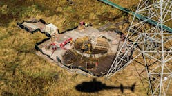
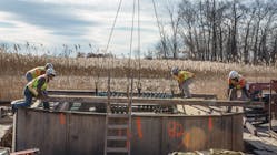
To reduce construction impacts to the wetland, a unique closed-cell cofferdam setup was employed at each site. These setups provided a stable platform for equipment in soft soils and groundwater, contained the drill cuttings and fluids from entering the wetland, and acted as a form for concrete placement during micropile cap construction. The cofferdams were constructed using helicopter-portable mini cranes and small excavators set onto local areas of crane matting. The use of this equipment significantly reduced helicopter hours, positively contributing toward schedule compliance and control of and overall project costs. A rotating drill carriage and micropile drill were set on the cofferdam and used to install micropiles in an array of vertical and battered piles.
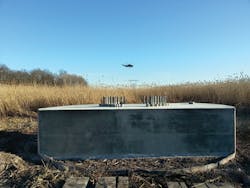
Following micropile installation, the drill and drill carriage were removed from the site to allow for tying of rebar form construction. A preconstructed anchor-bolt cage was flown to the site and supported by the cofferdam. Concrete was cast from crane-type concrete buckets. An accelerated high-strength concrete mix was chosen to ensure sufficient strength prior to form removal. Poles could be set less than one week following placement.
Project Success
The use of micropile foundations and helicopter-portable tubular steel poles allowed the project team to meet an aggressive construction schedule within the Troy Meadows wetland. Foundation work was completed ahead of schedule, and all seven monopoles were erected by Kh&m and its helicopter provider in just three-and-a-half days.
The innovative design and construction methods used in this project allowed for work to be completed with minimal impacts to the protected habitat. Accessing foundation sites by helicopter eliminated 108,000 sq ft (10,034 sq m) of matted access roads and 120,000 sq ft (11,148 sq m) of matted work areas, reducing total impacts to the wetland by more than 5 acres (2 hectares). The use of the closed-cell cofferdams allowed foundation crews to contain drill cuttings and fluids, and created a minimal area of impact from drilling activities.
The 500-kV Troy Meadows segment went into service on April 1, 2014, and the full SRERP is expected to be in service by June 1, 2015. Once completed, the approximately 150-mile (240-km) transmission line will connect Susquehanna, Pennsylvania, to Roseland, New Jersey. It is expected to significantly improve reliability and relieve congestion in the area.
Steve Davidow ([email protected]) is the vice president of engineering at Crux Subsurface. As a member of the executive team, he oversees all engineering activities and serves in an advisory role with project management and project controls. He has more than 15 years experience in infrastructure and commercial structure design, and holds BSCE and MSCE degrees from Washington State University. He is a licensed professional engineer in 30 states.
John Ribardo ([email protected]) is director of transmission projects for Public Service Electric & Gas Co. He has over 25 years of experience building T&D and generation projects, including positions in engineering, construction management and project management. He has BSCE and MSCE degrees from New Jersey Institute of Technology and an MBA from Seton Hall University, and is a licensed professional engineer in New Jersey. Since February 2008, he has been project director for the Susquehanna to Roseland Project.
Companies mentioned:
Burns & McDonnell | www.burnsmcd.com
Crux Subsurface | www.cruxsub.com
Henkels & McCoy | www.henkels.com
Kiewit | www.kiewit.com
Public Service Electric & Gas Co. | www.pseg.com
Sidebar: What Is a Micropile?
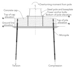
Micropiles are a small-diameter — typically less than 12 inches (305 mm) — high-capacity drilled and grouted replacement pile, reinforced with a threaded bar and steel casing. They are constructed by drilling a borehole through overburdened material and into a bearing stratum, placing reinforcement and grouting. They are capable of resisting axial tension and compression with applied lateral load.
Micropiles have a cased upper section, composed of steel tubes, and an uncased lower bond section, which develops friction with the surrounding bearing stratum. The cased section interacts with the surrounding soil or rock to provide lateral capacity to the foundation. The piles also are reinforced with a high-capacity threaded steel bar, which extends from the top of the pile through the lower bond section, transferring axial force through friction with the grout and ground. The pile group works in tension and compression to resist overturning.
