Evaluating Splice Integrity
If a conductor sleeve fails on a 345-kV line on a cleared right-of-way in the middle of the woods and no one sees it, does it cause an outage? In the case of American Transmission Co.’s Morgan-Plains transmission line in northeastern Wisconsin, U.S., it did. The outage occurred around noon on a clear day in February 2015. A helicopter inspection following the event revealed a two-stage compression conductor sleeve installed in 1968 had failed, and the conductor had fallen to the ground within that span. Crews repaired the line by splicing in new conductor.
The integrity of a two-stage compression sleeve depends on several factors:
• Proper cleaning and roughening of the conductor strands
• Use of appropriate compression dies for the sleeve type
• Use of a proper corrosion inhibitor
• Proper centering of the steel inner core within the sleeve.
According to the Electric Power Research Institute, the most critical misstep is a lack of inhibitor compound in the strands of the conductor.
An analysis of the failure on the ATC line revealed the aluminum-sleeve body had not been installed properly; it was not centered over the splice and steel core. Because the analysis revealed the potential for other incorrect installations, the utility undertook a deeper examination of the 69-mile (111-km) line.
Line Inspections Reveal Defects
A helicopter flew the entire line to conduct an infrared inspection and to identify additional defective sleeves. The inspection revealed two more sleeves were about 18°F (10C°) above the conductor temperature, which indicated the sleeves were not performing properly and could fail. Classic Connectors’ ClampStar shunts were installed over the hot sleeves to restore electrical and mechanical strength immediately.
Because this line is integral to the reliability of the ATC system in northeastern Wisconsin and the Upper Peninsula of Michigan, the utility decided to inspect all the remaining sleeves using Ohmstik Plus. The SensorLink Ohmstik Plus is a live-line, hot-stick-mounted micro ohmmeter used to measure the resistance difference between the conductor and its sleeves. Any sleeve with a resistance greater than or equal to the resistance of the conductor signals the sleeve is not performing adequately.
Crews Use Live-Line Micro Ohmmeter
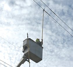
Using the Ohmstik Plus requires there be physical access to the sleeves being inspected. In ATC’s case, all inspections were performed using a three-person crew and a bucket truck. The sleeves in spans inaccessible by bucket truck were inspected with the Ohmstik Plus mounted to an extendable hot stick. The Morgan-Plains line consists of H-frame structures with all three phases easily accessible from the ground.
Once the crew was beneath the sleeves, obtaining the measurement of the sleeves was relatively simple. The linemen took three readings per sleeve using the Ohmstik Plus. By holding the device against the conductor for approximately 5 seconds, the Ohmstik recorded amperage on the line and conductor resistance. Then the linemen held the Ohmstik Plus against each end of the sleeve, recording amperage and sleeve resistance.
Crews inspected 281 sleeves over four days. Of those sleeves, 253 were found to be operating normally. However, testing revealed 32 sleeves had resistance greater than or equal to the line resistance, which indicated those sleeves were in need of attention. The resistance across a connector should be less than the line resistance. According to IEEE standards, a connection is considered to have failed electrically if the resistance is the same or greater than the line, a resistance ratio (RR) of 1.0 or greater. With a RR of 1.0, the splice may be cooler than the adjacent conductor, but it is a definite indication of a deteriorating connection. The RR of the defective sleeves on the Morgan-Plains line ranged from 1.00 to 7.95.
A connection with a RR of 7.95 is very high and in the thermal failure zone. The resistance is so high that much of the current is being conducted in the steel core wire, which is probably annealed. The only reason these sleeves had not yet physically separated is likely because of the relatively low load current on the line. Eventually, the fitting would become hot enough to anneal fully and fail under normal line tension.
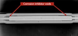
ATC analyzed the sleeves with the highest RR using direct radiography during the next line outage. The images indicated that the corrosion inhibitor that must be injected into the sleeve prior to crimping had been injected into the sleeve afterward. This was evidenced by the fact the cavity inside the sleeve was not fully packed with the inhibitor. Because of the voids present on either side of the inner cavity, it is possible for water and other contaminants to enter the sleeve body and accelerate corrosion, which can lead to premature sleeve failure.
Ohmmeter Complements Infrared
Why did infrared not identify the 28 sleeves the Ohmstik Plus found to be defective? The Morgan-Plains line design is bundled (two conductors per phase) 795 26/7 aluminum conductor steel-reinforced (ACSR) Drake conductor, which was carrying approximately 22% of its rated load when the infrared thermography was captured. Wind speed was about 5 mph (8 kmph), gusting to 17 mph (27 kmph), which is considered a moderate breeze. It is quite possible the relatively low load on the line, combined with the effect of the breeze, could have cooled the sleeves sufficiently so they would not present on an infrared image as being warmer than the conductor.
Infrared remains an excellent, cost-effective tool for the bulk inspection of transmission line and substation equipment. It can quickly indicate thermal anomalies for further investigation, but with a few caveats:
• The equipment being inspected must be loaded sufficiently so the potential for a temperature differential is increased.
• Wind has a cooling effect, more so on the conductor sleeve than on the conductor itself because of the sleeve’s larger diameter and resulting exposure to the wind.
• Conductor sleeves tend to be shinier than the conductor on which they are installed. Because the sleeve is shinier, it does not give off as much heat as the duller conductor.
When using infrared technology to inspect sleeves on bundled conductors, crews need to be aware of an anomaly. As the resistance in a sleeve increases, the electrical current, seeking the least resistive path, will naturally create an imbalance in current between the two sub-conductors. This imbalance may result in a marginally good connector on the heavily loaded side appearing hotter and the truly bad splice being missed. Because the Ohmstik provides an amperage reading, not a thermal reading, this phenomenon is easily detected.
While the Ohmstik Plus demonstrated its value in this particular instance, it has its own set of considerations. To use it, crews need access to the sleeves being inspected; if using a bucket truck, the truck will need to be able to access the terrain immediately under the sleeves. Accessing certain areas with a bucket truck can harm the underlying terrain — crop or lawn damage, for example — and access to the sleeves themselves can be an issue.
To date, ATC has only used the device to inspect sleeves on conductor mounted to H-frame structures, so all the sleeve locations have been horizontal and relatively easy to access. If the sleeve were on a double-circuit line with a vertical-conductor orientation, such as on a monopole, it would be a challenge to reach the middle or top phases safely from below.
ATC Plans Future Inspections
The Ohmstik Plus has proven to be an invaluable tool to help ensure reliable operation of the ATC system. The utility is contemplating a potential program to inspect sleeves that exist over sensitive spans — defined as those near dwellings, commercial buildings, roads, railroads or recreational trails — will be inspected using the tool. Infrared is an integral part of ATC’s inspection program, and ATC continues its five-year cycle of systemwide infrared inspection.
Acknowledgement
The authors would like to thank Janssen Baij, senior maintenance engineer at ATC, for coordinating the Ohmstik Plus inspection and radiographic analysis detailed in this article.
Greg Hicks is an asset support engineer at American Transmission Co., responsible for program management of various asset maintenance programs, including conductor sleeve management, corrosion inspection and mitigation, and umanned aerial system inspection of transmission line hardware. He holds a MBA degree and a bachelor’s degree in industrial engineering from Marquette University.
Joe Renowden earned a BSEE degree from Tri State College in 1970, and is a registered professional engineer, a certified fire and explosion investigator, and a senior member of IEEE. After a career as a project engineer, standards engineer and reliability leader at Florida Power & Light — where he acquired expertise on all the components, functions and malfunctions of what are now commonly referred to as transmission assets — he founded JDR Engineering Inc. He has conducted and analyzed Ohmstik survey measurements on transmission lines since the commercialization of the instrument and provided mitigation recommendations based on the results.
IEEE Study Replicates Real-World Results
An IEEE paper has shown the relationship between conductor temperature, ambient temperature, wind conditions, and conductor and sleeve emissivity. The study, “Improving Results of Thermographic Inspections of Electrical Transmission and Distribution Lines” — presented by John Snell and Joe Renowden at the IEEE 2001 Conference on Transmission & Distribution Construction, Operation & Live Line Maintenance (ESMO), 2000 28C-TPC-17 — had the following variables:
• Resistance ratio of 3.0
• Ambient temperature of 50°F (28°C)
• Wind speed of 13 mph (21 kmph)
• 795 26/7 aluminum conductor steel-reinforced (ACSR) Drake conductor
• Conductor and sleeve emissivity of 0.7.
The temperature of the sleeve was calculated to be 2.8°F (1.6°C) higher than the conductor. In the unlikely event this splice would have been detected by an infrared survey, it would not have been characterized as hot. If the sleeve were in practical use, it should have been scheduled for shunting, with a resistance ratio of 3.0.


