AEP’s BOLD Response to New Industry Challenges

The transmission grid has experienced ongoing and dramatic changes as a result of open access, regional markets and changes in the nature and location of generation sources. Widespread outages caused by natural events and the threat of physical attacks have driven the need for greater resiliency. At the same time, the public resists construction of new lines because of aesthetics and other reasons, especially higher-voltage lines that more efficiently deliver bulk power over long distances. Despite all of these drivers for change, transmission line designs have remained relatively unchanged over the last 40 years. Until now.
Forces Driving Change
U.S. electric utilities today are engaged in transmission projects to enhance reliability, integrate new sources of generation and modernize the nation’s electric grid. When new energy sources are remote from load centers, transmission must deliver the power reliably and efficiently over longer distances. These trends are in response to mandatory reliability and renewable portfolio standards, environmental and efficiency demands, grid security and resiliency needs, and continued load growth.
In addition, the industry is adapting to the U.S. Federal Energy Regulatory Commission (FERC) Order 1000, which eliminated an incumbent utility’s right of first refusal to build certain transmission facilities in its service territory, thus creating both challenges and opportunities. Concurrently, the U.S. transmission infrastructure is aging; significant renewal and rebuilding is underway and will continue. Most rebuilding will make use of existing rights-of-way (ROW) as a result of regulatory and public pressures to reduce the impact of line siting.
The Loadability Challenge
The power transport capability, or loadability, of an alternating-current transmission line is governed by thermal, voltage-drop and steady-state stability limitations. An outcome of the conductor or terminal equipment selection process, thermal rating is most limiting for lines shorter than 50 miles (80 km). Longer lines are limited primarily by voltage-drop or stability considerations, both of which are affected by the length-dependent line impedance.
The most effective way to reduce line impedance and improve loadability is to raise the transmission voltage class. However, this method faces public opposition, particularly when plans call for the highest available voltage transmission. Left with few options, utilities choose lower-voltage lines supported with series compensation to reduce transmission path impedance and attain required power-transfer objectives.
Traditionally, series compensation has served as a near-term remedy to stretch system capability until implementation of a longer-term solution or as a substitute for higher-voltage transmission. This is especially true when moving large blocks of power point-to-point over long distances. However, these applications may lead to operational issues such as sub-synchronous resonance (SSR) and sub-synchronous control interactions (SSCI), which pose a risk to electric machinery and can lead to instabilities. Other concerns include system protection complexities, maintenance or spare equipment requirements, limited life expectancy, electrical losses and future grid expansion issues such as tapping the compensated line.
The BOLD Solution
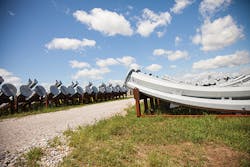
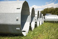
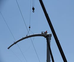
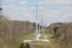
The high-capacity, high-efficiency BOLD (breakthrough overhead line design) solution features a streamlined, low-profile structure with phase-conductor bundles arranged into compact delta configurations. The structure consists of an arched crossarm supporting both circuits set atop a tubular-steel pole, imparting a more favorable aesthetic appearance. BOLD can support either double-circuit or single-circuit (that can be expanded in the future to double-circuit) lines. Although the first BOLD development project is a 345-kV design, other voltages such as 230 kV are also included in the design series.
The average 100-ft (30-m) 345-kV structure is about one-third shorter than a traditional double-circuit design. Each phase contains multiple conductor bundles 18 inches to 32 inches (457 mm to 813 mm) in diameter. The separation distances among the three phases are as low as 14 ft (4.3 m) and are maintained using two interphase insulators per circuit; standard insulators attach each of these bundles to the crossarm and tubular structure bodies. The crossarm supports two shield wires positioned to provide zero-degree shield angle to the outmost phases.
BOLD’s patented configuration packs roughly 50% more capacity into the ROW. It markedly improves line surge impedance loading (SIL), lowers series impedance and reduces ground-level electromagnetic field (EMF) effects. SIL is a convenient yardstick for measuring relative loadability among alternative line design solutions. BOLD uses three conductors per phase at 345 kV, offering significant gains in line loadability and energy efficiency for long-distance and local applications.
Although a typical 150-ft (46-m) 345-kV ROW may be used, the low-height, eye-catching profile can fit within a 105-ft (32-m) ROW, a potential reduction of nearly one-third of typical ROW width. These visual benefits are expected to improve public acceptance of new transmission projects.
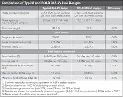
BOLD vs. Traditional Design
The table summarizes the physical and electrical characteristics of a traditional 345-kV double-circuit line design and the BOLD solution (one of the three BOLD options). Note the new design’s significant improvements in SIL (43% increase), impedance (30% reduction) and energy loss (33% lower resistive loss), which most influence line loadability and efficiency. These are key advantages for a transmission lines built to carry power over long distances.
The table also compares thermal ratings, EMF and audible noise emissions. Especially notable is the 51% reduction in ground-level magnetic field. This is an area that continues to receive considerable attention in line-siting regulatory proceedings.
By using three-conductor phase bundles, significant gains are attained in thermal capacity and line efficiency, resulting in lower operating temperatures. BOLD improves overall system performance by unloading higher-impedance/lower-capacity lines. Alternative designs are possible, using between two conductors per phase and four conductors per phase.
When compared with conventional designs, the BOLD 230-kV solution will offer even greater relative electrical advantage in line impedance and loadability.
In projects that normally would require series compensation, an added bonus is the prevented need to install and maintain or replace the compensation equipment (including SSR/SSCI mitigation) over the long term, considering the long life expectancy of a transmission line. The associated financial impacts can be substantial over the full life of the line.
Prototype Development and Testing
BOLD development began with exhaustive analysis and design efforts, followed by extensive laboratory testing. American Electric Power (AEP) teamed with Hubbell Power Systems and Valmont Industries on some aspects of the development to ensure the new line design met established performance requirements and would have the requisite structures, insulators and hardware ready for practical installation.
Hubbell Power Systems tests conducted at the Wadsworth, Ohio, facility confirmed the modeled insulator hardware corona performance and found it met AEP’s design criteria. Valmont Industries fabricated the tubular-steel structure. BendTec and American Pipe Bending, Valmont subcontractors, provided crossarm bending services using an induction heating process. Mechanical tests of the structure were conducted at Valmont’s facility in Nebraska.
The Electric Power Research Institute Power Delivery Laboratory in Lenox, Massachusetts, tested a full-scale single-circuit prototype of BOLD for power frequency, corona effects, audible noise, lightning and switching surges, and phase-to-phase insulation.
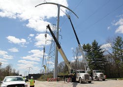
BOLD Deployment
AEP Transmission is deploying 121 BOLD structures for a 22-mile (35-km), 138-kV rebuild with a 345/138-kV hybrid line design between Sorenson and Robison Park stations, forming an extra-high-voltage loop around Fort Wayne, Indiana. A 6.5-mile (10-km) segment of the rebuild was energized in the summer of 2015; the entire line will be in service in June 2016. The improvements will reduce potential voltage and overload problems, and prepare the local grid for future deliveries of energy from wind farms in Indiana and northwestern Ohio.
AEP’s first 345-kV double-circuit application of BOLD will be a 9-mile (14-km) rebuild in northern Indiana, targeted for completion in June 2018. BOLD structures are being considered for a third rebuild in Indiana and a new project in southern Texas. In 2015, AEP formed BOLD Transmission LLC, a subsidiary aimed at marketing the new line and providing the industry with innovative transmission solutions.
A 230-kV design solution is being tested electrically and will be available for deployment in the near future.
Acknowledgments
Special recognition is given to AEP’s senior executive leadership — Nick Akins, Lisa Barton and Mike Heyeck (retired) — for their encouragement and strong support related to this new transmission line design. The authors also recognize the following team members for their contributions: Dave Parrish, John Ng, Bruce Freimark, Eric Engdahl, John Liebrecht, Tim Summers, Tony Swaneck, Carlos Casablanca, Carol Liu, Sanjoy Sarawgi, Larry Anderson, and members of AEP Transmission management Jeff Fleeman, Evan Wilcox, Jeff Momme, Bob Bradish and Scott Moore.
Richard Gutman ([email protected]) has been employed by American Electric Power since 1968 with responsibilities for advanced transmission studies and technologies, extra-high-voltage and interconnection planning, and generation planning. He is an advisor on EPRI’s EMF/RF Area Council and has received EPRI’s Innovators Award for advancing new technologies. He received a BSEE and a MSEE degree from Polytechnic Institute of New York, and an MBA degree from The Ohio State University. He completed the electric power systems program at Power Technologies Inc. and the AEP/OSU management development program at Ohio State. He is a member of Tau Beta Pi engineering, Phi Kappa Phi interdisciplinary, and Beta Gamma Sigma business honor societies, a member of the New York Academy of Sciences and a life senior member of IEEE. He is a licensed professional engineer in Ohio and New York.
Meihuan Zhu Fulk ([email protected]) joined American Electric Power in 2006 and is a principal/structure engineer in the transmission line standards group, with responsibilities for structure and foundation design and analysis, conductor motion control and fatigue design. She received a bachelor’s degree in structural engineering from Tongji University and a Ph.D. degree in engineering from Louisiana Tech University. She is a licensed professional engineer in Ohio; a member of IEEE, ASCE and AISC; and holds seven patents.