A New Way of How: Secondary Voltage Control
The distribution system, a key subset of the overall electric grid, provides power to residential, commercial and industrial customers. Voltage and reactive power management and control have been done traditionally from the primary side by using substation transformers with load-tap changers (LTCs), voltage regulators and capacitor banks. In recent years, advanced distribution applications such as conservation voltage reduction (CVR) — implemented to achieve demand and energy reduction by lowering service voltages — started presenting new operational issues.
In addition, increased penetration of distributed generation such as residential solar photovoltaics (PV) and the increased use of power electronics-based devices have resulted in new power-quality challenges. Resolving these new operational issues with primary devices became a less-than-desired approach because primary voltage levels tend to be too coarse and slow to resolve this new generation of localized, variable voltage disturbances completely.
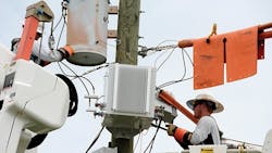
Duke Energy initiated a series of pilots that included the installation of three low-voltage power electronics devices from Gridco Systems, called In-Line Power Regulators (IPR), to explore the effects of the devices on a variety of challenges in secondary distribution circuits, including secondary voltage regulation, reactive power flow, voltage and current harmonic mitigation, and power-quality event mitigation.
The In-Line Power Regulator
The IPR is installed on the secondary side of the distribution transformer, and it has a source and a load side. The architecture includes both series and shunt regulating components. The series regulating component for voltage regulation (±10%) uses the source voltage as a control input and regulates the voltage on the load side to the desired level. The shunt current source provides ±5 kVAR support and regulates the power factor on the secondary. The current source uses the reactive power on the load side as a control input and regulates the reactive power on the source side.
The objective of the pilot projects was to understand whether decoupling of the distribution system’s primary and secondary sides in the area with operational challenges could resolve these problems. To validate the results of the trials, data generated by the IPR was captured by power-quality meters from Power Sensors Ltd. and SATEC. Metering was installed on both sides of the IPR and on the customer premises.
Pilot 1: Voltage Regulation for CVR
In recent years, implementation of CVR programs resulted in tighter voltage control on the distribution feeders in the lower part of the American National Standards Institute (ANSI) range. Measurement of the customer voltages has been enabled by the installation of advanced metering infrastructure (AMI) meters. However, the ability to control voltage is a function of operating the devices at a relatively coarse level on the primary side, where changing the voltage for one customer means changing it for all customers on the feeder. This lack of granularity in voltage control limits the extent to which a CVR implementation can drive lower voltages across the system to all customers while maintaining voltage compliance for all.
Resolving this issue involves not only a monitoring capability, such as AMI on the system secondary, but also an ability to regulate voltage on it. Traditional methods for increasing the secondary voltage include increasing the distribution transformer size, reconductoring the secondary cables with higher gauge lines, extending the primary, or splitting the secondary bus and installing an additional transformer. These options generally require an outage and provide a relatively small voltage improvement. Because these are fixed, passive improvements, they may not meet future needs of the local secondary circuit, such as new electric-vehicle charging stations.
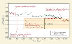
In order to control the voltage on the system secondary without controlling the primary devices, as part of the first pilot project, an IPR was installed on a distribution system feeder on the secondary side of a 25-kVA transformer that feeds five residential customers. The IPR was tested in two modes: a fixed voltage set point and a deadband voltage set point. The IPR installed on the secondary side can regulate the downstream voltage similar to the LTC or voltage regulator used on the primary side.
The main difference between the IPR and electromechanical voltage regulators for medium-voltage use is the IPR is a power electronics-based device, it has no moving parts, and therefore, has no limit on the number of operations. The IPR also has better voltage accuracy with the ability to regulate the voltage within 0.5% and operate in just over one cycle, much faster than LTCs and line regulators.
When the IPR is in bypass mode, its output voltage tracks the input voltage. The device is monitoring and reporting data, but it is not regulating in this mode. When the IPR was enabled in the set-point voltage regulation mode (1.0 p.u.), the load voltage was being regulated at the set point, regardless of the value of the source voltage. Enabling the IPR in voltage deadband mode (between 1.0 p.u. and 1.025 p.u.) enabled the voltage regulation within the desired voltage limits. The deadband mode was found to be the preferred mode for the low-voltage regulation.
As noted before, the total kilovolt-ampere-reactive capability of the IPR is up to 5 kVAR for either capacitive or inductive reactive power. Traditionally, utilities have not been trying to manage to a desired power factor on the secondary side. However, given the distribution losses usually tend to be in the 6% to 8% range, this functionality of the IPR could reduce some of the reactive losses. For the purpose of the pilot, the IPR was tested in two power factor regulation modes: fixed power factor and fixed kVAR output; both modes operated as expected.
Pilot 2: Voltage Regulation for Residential PV
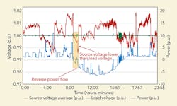
A typical voltage drop on the system secondary is 1.5% to 3.5%. Adding a PV on the customer premise can result in reverse power flow leading to the customer voltage being greater than the voltage on the transformer secondary. If the PV generates even more power or the load decreases, the voltage rise increases. In the second pilot, a site with customer-owned PV was selected for an IPR installation, and the system secondary experienced reverse power flow conditions. The IPR kept the voltage at a constant level (1 p.u.), independent of the power flow direction and source voltage.
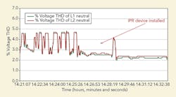
High levels of harmonics can result in reduced equipment life. Because of their nature, all power electronics devices introduce harmonics to the distribution system, predominantly current harmonics. Given that the IPR has the capability to improve the power quality on the secondary side by reducing and potentially canceling the 3rd, 5th and 7th voltage and current harmonics, the pilot project also involved enabling voltage and current harmonic mitigation modes during the initial six months of operation.
Based on the results from the pilot, the IPR significantly reduced the harmonics created by the PV inverter. For the locations with residential PVs, the optimum operating mode was found to be the voltage control in either the deadband or fixed set-point mode, along with voltage and current harmonic mitigation mode.
Pilot 3: Power Quality Event Mitigation
In the third pilot, an IPR was installed next to a distribution transformer that is electrically adjacent to a metal shredding facility, connected to the primary feeder circuit through its designated transformer. During shredding operations, voltages on the circuit would have significant variation (sometimes in excess of 20 Vac on a 240-Vac base), causing the circuit to be operated on the higher side of ANSI limits.
During the voltage fluctuation, the lights on a nearby traffic signal would malfunction by flashing yellow because the traffic signal and its sensitive control equipment were on the same secondary, where the IPR is now installed. In instances when the voltage fluctuation caused the voltage to go below 232 V, the traffic signal would go dark, which in turn locked out the lights and resulted in a state police officer being called in for traffic control and the state highway transportation department having to come to reset the equipment.
Once the IPR was installed on the transformer feeding the traffic light, and commissioned in the voltage set-point mode and voltage and current harmonic mitigation mode, the significant improvement in voltage stability was noticeable immediately.
In addition to the rapid voltage change, the metal shredder also introduces harmonics into the primary side, which impacts the performance of the traffic light equipment. The IPR aids in the mitigation of harmonics but has some limitations preventing it from completely removing the harmonics at this site because the majority of the harmonics are above the 7th harmonic (in this case, the 9th, 11th and 13th harmonics).
The IPR firmware actively mitigated the 3rd, 5th and 7th harmonics, specifically the voltage harmonics on the load side (traffic light side) of the device and the current harmonics on the source side (utility side) of the device; harmonic mitigation addresses steady-state harmonics only. For this application, the IPR has kept the voltage at acceptable levels for the traffic signal, which has not gone into the flashing state or turned off since the IPR installation. This reduces calls for the local state police, the highway department and the utility, and it improves public safety for that site.
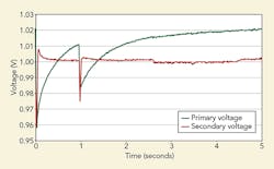
An additional benefit discovered from deploying the IPR during the pilot project was voltage sag mitigation caused by the system primary. The IPR regulating range is within 55% to 125% nominal voltage, and it can provide ±24-V buck/boost within three cycles. In the process of testing, the distribution system experienced a fault on the primary side. The IPR responded by regulating voltage in the first cycle and providing a full 10% boost within the first three cycles, while it took a lot longer for the primary voltage to reach its level before the fault. During the couple of voltage sag events on the primary side that were more significant, the IPR provided up to 24 V of voltage boost on the customer side.
Future Efforts
Duke Energy has piloted the IPR in three different applications and proved that the IPR can resolve technical issues associated with these applications while providing a positive impact. In this case, decoupling the primary and secondary distribution system by installing the IPR proved to be a successful approach. Duke Energy is currently investigating several enhancements such as mitigating higher harmonics, performing sub-cycle voltage regulation, increasing capacity and having a medium-voltage three-phase power electronics-based volt/volt-ampere-reactive regulating device.
Aleksandar Vukojević is the manager of emerging technologies office at Duke Energy. His duties involve developing, installing, testing and evaluating new technologies. Vukojević is pursuing a Ph.D. in electrical engineering at the University of North Carolina at Charlotte.
Joseph Grappé is a lead power-quality engineer at Duke Energy and has more than 10 years of experience in the power utility field. Grappé regularly deals with power-quality issues involving residential, commercial, industrial and governmental customers.
Editor's note: The authors would like to acknowledge Bob McFetridge from Gridco Systems for his contribution to this article.