In the last decade, volt/volt-ampere-reactive (VAR) control became one of the most desirable smart grid applications. Its primary objectives include voltage control, VAR or power loss minimization control, and conservation voltage reduction (CVR), which results in energy demand reduction.
In 2012, Baltimore Gas and Electric (BGE) initiated a smart grid pilot project with the main objective of CVR implementation. The project included installation of new capacitor bank controllers, voltage regulators, end-of-line metering and head-end CVR algorithms, and measurement and verification analysis. However, implementing the CVR project and operating under the voltage and reactive power constraints resulted in numerous lessons learned, some of which were unexpected.
Demand Not Always Reduced
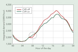
The main objective of CVR is to reduce feeder voltage, which, in turn, should result in reduced energy consumption. However, in certain situations, enabling CVR can result in increased kilowatt-hours. There are several reasons for this phenomenon, but, most likely, load composition, circuit construction and customer demographics are the main contributors.
For example, one of the most common loads in every household is a television. A recent CVR study by Battelle showed that lowering the voltage results in increased energy consumption of plasma and liquid-crystal display TVs. A day on-day off analysis on a feeder can show, by enabling CVR, the result is actually increased energy consumption during short periods. Furthermore, analyzing benefits on each phase is the best approach. Analysis on all three phases almost always showed positive CVR benefits. However, learning about any negative CVR factors provides further insights into the feeder loading, demographics and so forth.
Capacitor Bank Monitoring a Must
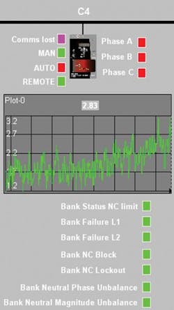
Capacitor banks fail as a result of a blown fuse, shorted capacitor can or stuck switch. When a system has no communications with field devices, capacitor bank failure cannot be detected immediately. However, with the communications to capacitor bank controllers required by CVR, monitoring a neutral current transformer (CT) can significantly improve capacitor bank failure detection. BGE used new Beckwith M-6283A capacitor bank controllers equipped with two-way radio communications by using the CalAmp VanGuard 3000 radio with a GPS and dual cell provider. With this equipment, it is now possible to detect a failed capacitor bank immediately by monitoring neutral CT.
BGE has implemented capacitor bank controllers from Beckwith that can switch banks either single phase or three phase, use voltage and current sensing from all three phases and act as fault circuit indicators. The firmware implemented not only enables notification there is a problem with a bank, but it also specifies whether the problem is a blown fuse, failed switch or can failure per each individual phase. Note that BGE capacitor banks do not have auxiliary status switches, and analysis for the switch status and failure are done based on the neutral current angle and magnitude.
Reactive Power vs. Real Power
Most of the time, CVR is associated with voltage reduction, and the topic of voltage is the primary concern. However, one additional benefit of CVR is better management of reactive power flow.
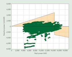
In general, BGE’s operating procedures require power factor on the low side of the transformer to be 0.95 lagging or better when transformer loading is less than 90% of estimated peak and at least 0.98 leading for the loading above 90%. Using the data from the pilot for real and reactive power, it is possible to determine whether the feeders have enough reactive power support and the CVR algorithms are operating within the desired power factor region.
The CVR algorithm used during the pilot was only capable of specifying the symmetrical power factor, which was set between 0.95 leading and lagging. But, data analysis from the pilot showed it was not uncommon for the actual power factor to deviate substantially from the specified value. Ideally, all real and reactive power pairs would fall within the desired limits. However, quite a few operating points are outside the desired operational region.
CVR Benefits Feeders without LTCs
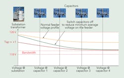
More than 90% of BGE’s distribution system is built with transformers without load-tap changers (LTCs) or any voltage regulators at the feeder head end. Achieving CVR with this type of system architecture is challenging. To reduce energy consumption, BGE invented new methodology that includes substation transformer tap change, along with control of field capacitor banks. In this case, the CVR was achieved by operating the field capacitors so the average voltage across all the primary line voltage sensor points is at its minimum.
In addition, the CVR software also has a routine to determine the substation transformer’s optimum tap position at any point in time. Using this approach, it was possible to change the tap in a de-energized state and realize further energy-reduction benefits.
However, changing the substation tap lowers system voltage, but to keep the primary voltages above the desired minimum, it is now necessary to switch more capacitor banks, which in turn results in the leading power factor. To keep the power factor in the desired range, it is necessary to identify the upstream voltage-regulating device and increase the voltage coming into the substation, which reduces the number of capacitor banks that need to be switched on. As a result, the overall voltage reduction is lower than could be accomplished by the substation transformer tap change alone.
In addition, BGE’s implementation of capacitor bank controllers that can enable single-phase switching also could potentially allow for the tap change on the transformers with voltage imbalance.
Voltage Regulator Tap Operations
One of the objectives of the CVR also should be the minimization of the number of daily operations of LTCs and voltage regulators. During the pilot project, BGE experienced 29 daily operations on average, with a maximum number of operations reaching 65. BGE did not have a lot of experience with voltage regulators given that only seven feeders out of 1,250 feeders have voltage regulators on the head end, and, of these, five were installed during the pilot.
In addition, BGE has approximately 60 locations with voltage regulators on the system, but those devices rarely see any load under the normal conditions because they are located next to the normally open tie reclosers and used for voltage control during operation of automated restoration schemes. It is expected the acceptable number of daily voltage regulator operations should be 20 or less.
Data Granularity
The pilot CVR projects introduced the issue of voltage variation as a function of time at end-of-line locations. Many utilities are using the advanced metering infrastructure (AMI) data on 5-minute or 15-minute intervals to monitor CVR. Most of the time, these voltages are instantaneous values and, in some cases, average values. During the pilot, BGE tried to identify the optimum granularity of end-of-line AMI data needed for the CVR algorithms.
Analysis showed the ideal approach for CVR would be to use 1 minute of average data. As a result, less than 1% of all voltage reads within a minute, compared to the average value within the minute, were outside the ±1.2-V target range (1% accuracy). At the same time, for 5-minute data, this number is almost 4%; for 15-minute data, the number reaches almost 8%. This is important because the utility has to understand what level of risk it is willing to accept as the CVR algorithm might not operate under the correct voltage input data, thus resulting in device operation that might not be optimal.
Furthermore, obtaining the voltage data from the AMI network at a different granularity might require significant improvement to the AMI system, because most AMI networks are not built with very granular voltage collection data in mind. One possible approach might be to use 5-minute average voltage data to enable the CVR algorithm and use the last 1-minute data as an input to the CVR control module. This is just to ensure the CVR is using voltages as closely as possible to the existing data.
Voltage Sensing
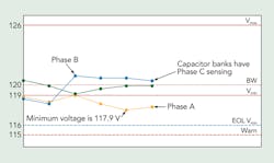
Most of the time, voltage sensing for the capacitor banks on the BGE system is obtained by measuring the voltage from a potential transformer (PT) usually located on the C phase. Station transformers with LTCs have their PT tapped off B phase. The result is capacitor banks are switched off a different phase (C) than the phase used for voltage lowering (B). Depending on the system imbalances, this could pose some additional operational challenges. To balance the feeder properly, BGE has started using the single-phase capacitor bank switching and voltage measurements from all three phases at the capacitor bank.
Capacitor Bank Placement
Before moving forward with a CVR implementation, one of the first tasks should be to determine whether the capacitor banks are at optimum locations. Because of the field factors, available space on the poles, capacitor banks usually are not placed optimally for the CVR. Today, several planning tools have the capacitor optimization placement algorithms.
Even though most of the systems are built for peak conditions, the reality is the system annually spends 1 hour in its peak state and probably 20 hours above 90% of the peak, adding the capacitor bank to minimize energy consumption during the above 90% of the system peak is probably not the best approach, because of the cost-benefit analysis. In addition, relocating the existing capacitor banks can further improve CVR savings.
Delta V Measurement
To enable new capacitor bank controller functionality, such as predictive blocking, capacitor bank controllers measure the voltage change at the start of operation. System planning standards allow only for a certain voltage change as a function of the operation of the capacitor bank (for example, 3% [or 3.6 V]). During the planning stage, this is normally calculated with the help of software, but the calculated value and field value could be significantly different. Field measurements of this voltage change showed, in some cases, results that were different compared to planning values. This could be used to make improvements in the feeder modeling software.
Predictive Block
Predictive block is a feature of the new capacitor bank controllers BGE used extensively during the CVR pilot project. Predictive block prevents the capacitor bank from operating if the voltage after operation will exceed a user-defined limit. The calculation is based on the current, voltage and delta V measurement. This feature was one of the main security measures implemented during the CVR pilot, so the system is protected from any undesired local or remote operations.
Potential Transformer Failure
During the CVR pilot, the head-end system measured numerous voltage points. However, even though the voltages on the primary were always within the desired limits, presenting the voltages as a function of the increasing impedance from the substation can reveal any anomalies in measurements.
One such anomaly was detected on one of the PTs whose voltage constantly measured 2 V higher than the two voltages on the capacitor banks that were upstream and downstream from the bank with which the PT was associated. Further analysis revealed the primary of the PT had two shorted windings; this, in turn, resulted in the CVR routine not operating optimally.
Single-Phase Switching
Most utilities that have implemented CVR use gang-operated capacitor banks with one 1-kVA transformer for a voltage sensor to provide power to the controller. If the feeders have voltage regulators at the feeder head end, this approach is appropriate in terms of achieving the energy-reduction objective. However, feeders without voltage regulators could be unbalanced at the substation. To resolve this problem, BGE worked with Beckwith and implemented single-phase operation functionality within the M-6283A capacitor bank controller.
Based on experience from the CVR pilot project, the new controller has the capability to measure three voltages, three line currents and neutral current, operate in gang or individual phase mode, and also act as a fault current indicator. In addition, based on the loading on each feeder, voltages can be different on different phases along the feeder. Having information from only one phase might not result in an optimum solution.
Benefits Evaluation
One of the most challenging tasks with respect to the CVR is the calculation of benefits. At present, no unique method exists for the evaluation of benefits. Some utilities use a distribution management system (DMS) load-flow-based model to evaluate the benefits while others use statistical methods such as proxy day or automated CVR protocol No. 1. However, when trying to estimate the potential savings across the whole system, not only is it necessary to look at historical voltages, but it also is necessary to look at the LTC/voltage regulator tap position. The combination of these two factors determines the maximum potential level of savings.
One of the most important lessons learned on the BGE system was that even though the voltages at some substations were in the 121-V to 126-V range most of the year, the tap position was at its minimum for almost 40% of the year. This limits potential energy reduction.
Voltage Balancing Index
One of the parameters BGE decided to include in its CVR algorithm was the minimization of voltage balancing index (VBI) as defined by the American National Standards Institute. This algorithm is normally executed after the CVR algorithm. Field trials with VBI in the algorithm showed if single-phase capacitor bank switching is used, VBI is reduced after the execution of the CVR algorithm. However, in cases where there is not a strong source and where voltage variations as a result of capacitor bank operations are higher, achieving true minimum VBI can be challenging.
Lessons in Action
During the CVR pilot project, BGE learned a lot of lessons, some of which resulted in operational efficiencies. Moving forward, BGE will implement some of the lessons learned during the pilot project.
Acknowledgements
The authors would like to thank Greg Henry from Black & Veatch and Andrew Hanson from The Structure Group for their contributions to the analysis of cost-benefits for the CVR pilot projects, and Aleksandar Vukojevic, manager of the smart grid distribution automation and technology department at BGE, for his contributions to the article.
Jonathan Short ([email protected]) is a lead distribution automation technician in the distribution automation and voltage-quality unit at Baltimore Gas and Electric. He has 20 years of experience in the utility business, specializing in distribution automation, overhead and underground construction, and field implementation and integration of new smart grid technologies.
Michael Smith ([email protected]) is a lead engineer/work leader with Baltimore Gas and Electric’s automation and technology unit. He has 30 years of experience in the utility business, specializing in system protection, substation integration and supervisory control and data acquisition.
Companies mentioned:
American National Standards Institute | www.ansi.org
Baltimore Gas and Electric | www.bge.com
Battelle | www.battelle.org
Beckwith | www.beckwithelectric.com
CalAmp | www.calamp.com

